Spark plug for internal combustion engine designed to keep ignitability of fuel high

a technology for spark plugs and internal combustion engines, which is applied in the manufacture of spark plugs, spark plugs, electrical appliances, etc., can solve the problems of reducing the wear of noble metal chips per unit time, reducing the rate of increase in the size of spark gaps, and keeping the voltage required for spark plugs to discharge at lower levels. , to achieve the effect of reducing the formation of dimples, reducing the amount of wear of noble metal chips, and reducing the amount of noble metal

Inactive Publication Date: 2008-03-27
DENSO CORP
View PDF5 Cites 29 Cited by
  • Summary
  • Abstract
  • Description
  • Claims
  • Application Information

AI Technical Summary

Benefits of technology

[0051] Specifically, the noble metal chip has the portion tapering toward the top end thereof, in other words, the noble metal chip is made up of a thin top portion and a thick base portion joined to the ground electrode, thereby ensuring the higher degree of ignitability of fuel, as described above, and keeping the voltage required by the spark plug to discharge at lower levels.
[0052] The tapered base portion serves to minimize the formation of a dimple in the weld between the no

Problems solved by technology

The formation of the thick portion of the noble metal chip improves the conductivity of heat to a corresponding one of the ground and center electrode to decrease the wear of the noble metal chip and also result

Method used


Image

  • Spark plug for internal combustion engine designed to keep ignitability of fuel high
  • Spark plug for internal combustion engine designed to keep ignitability of fuel high
  • Spark plug for internal combustion engine designed to keep ignitability of fuel high

Examples


first embodiment

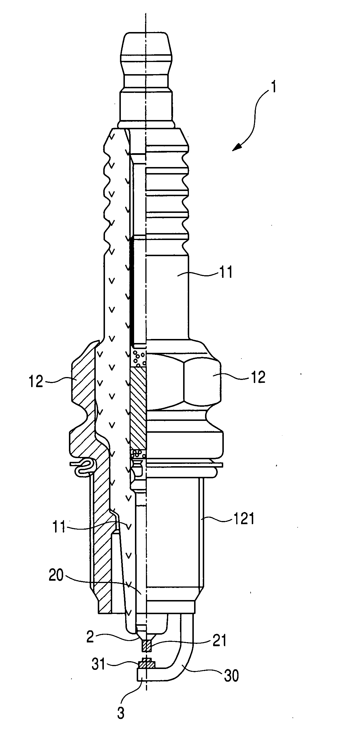
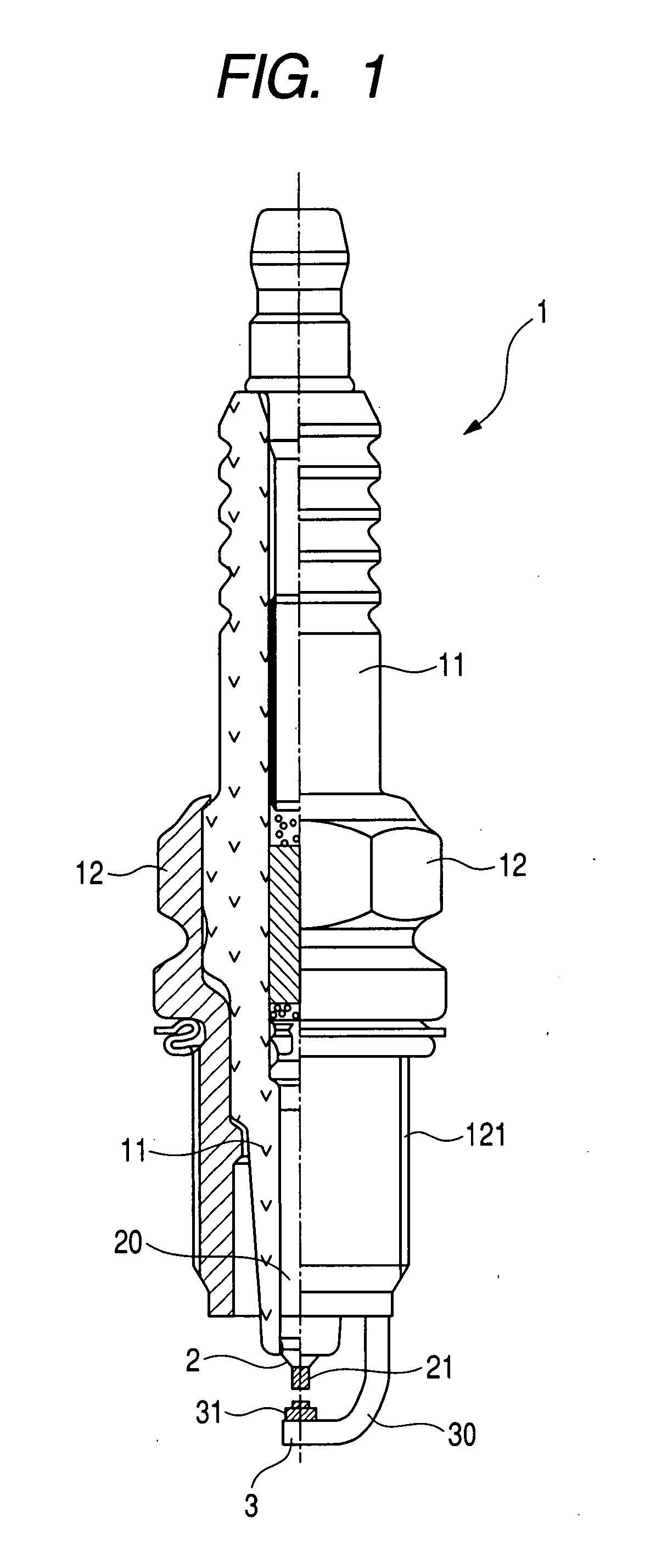
[0091] Referring now to the drawings, particularly to FIGS. 1 and 2, there is shown a spark plug 1 for internal combustion engines according to the invention which may be employed in automotive vehicles, cogeneration systems, or gas feed pumps.

[0092] The spark plug 1 includes a center electrode 2, a ground electrode 3, a porcelain insulator 11, and a metal shell 12. The center electrode 2 and the ground electrode 3 are opposed to each other to define a spark gap (also called an air gap) therebetween. The center electrode 2 and the ground electrode 3 have faces which are opposed to each other and to which a noble metal chip (will also be referred to as a center electrode chip below) 21 and a noble metal chip (will also be referred to as a ground electrode chip below) 31 are affixed, respectively.

[0093] A ground electrode body 30 extends from an end of the metal shell 12 to form the ground electrode 3. A center electrode body 20 extends from the porcelain insulator 11 and has a head ...

second embodiment

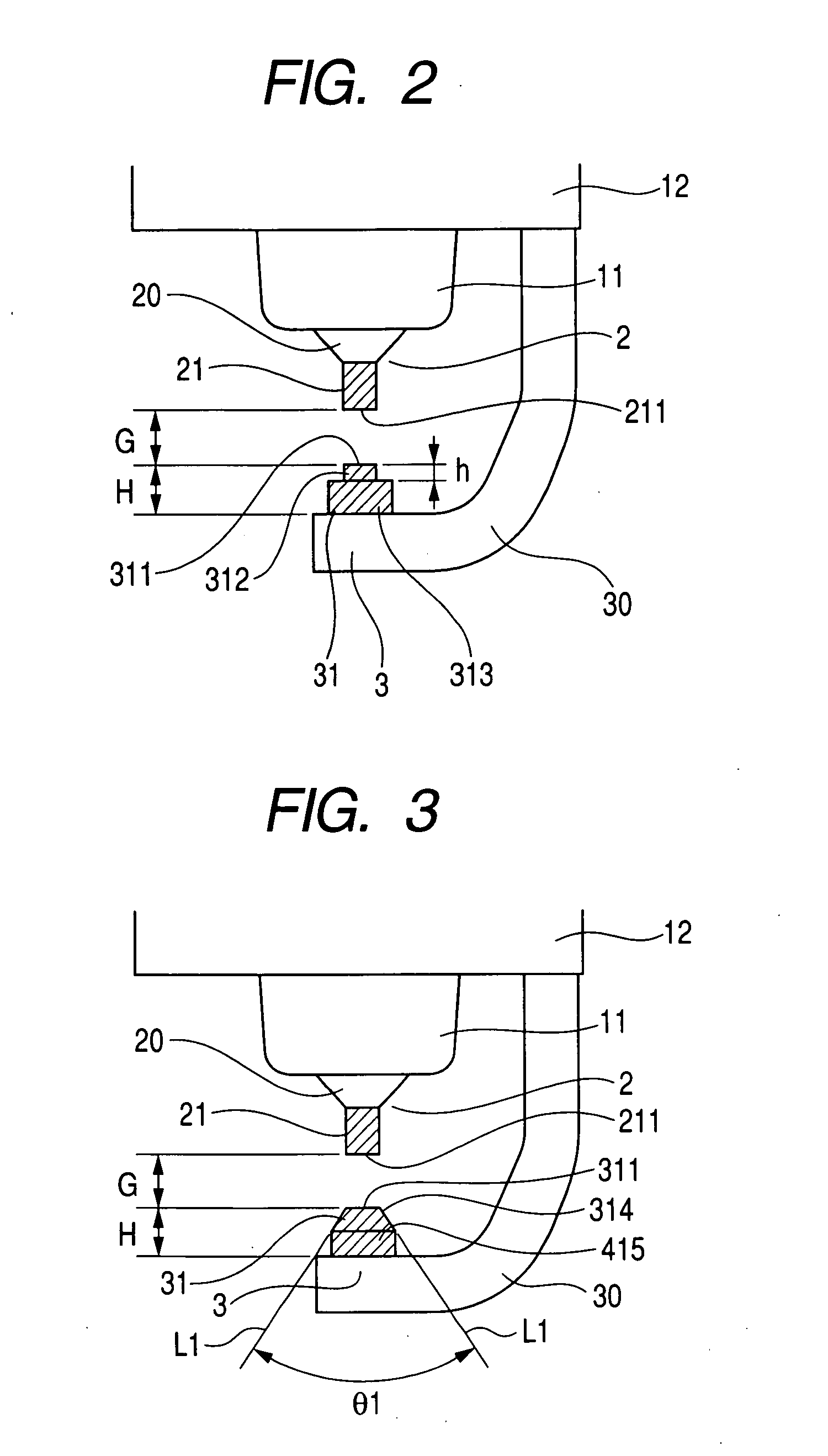
[0115]FIG. 3 shows the spark plug 1 according to the invention.

[0116] The ground electrode chip 31 is made up of a frusto-conical portion 311 with an annular tapered surface and a cylindrical base portion 415. The frusto-conical portion 311 has the top end surface 311 which extends perpendicular to the longitudinal direction of the spark plug 1 and has an area of 0.1 mm2 to 0.6 mm2. The sectional area of the center electrode chip 21 is also within a range of 0.1 mm2 to 0.6 mm2.

[0117] The length G of the spark gap between the top end surfaces 211 and 311 is greater than or equal to 0.5 mm (G≧0.5 mm). When G1, as clearly illustrated in FIG. 3, which lines L1 make with each other is preferably selected to meet a relation of θ1≦{100+200 (G−0.5 mm)}. The lines L1 are defined to extend along the tapered surface of the frusto-conical portion 314 and be opposed diametrically to each other across the center of the top end surface 311. When G≧0.6 mm, the angle θ1 is preferably selected to be...

third embodiment

[0179] FIGS. 16 to 20(d) show the spark plug 1 according to the invention in which the noble metal chip 31 welded to the ground electrode body 30 has formed on at least a portion of the periphery thereof a wall 315 tapering toward the noble metal chip 21 of the center electrode 2. The noble metal chip 31 in this embodiment is of a frusto-conical shape as a whole.

[0180] The noble metal chip 31 is laser-welded to the surface of the ground electrode body 30 and joined thereto through fused portions (also called weld nuggets) 316 each made of a mixture of materials of the noble metal chip 31 and the ground electrode body 30 melted together during the laser-welding.

[0181] Each of the area of the top end surface 311 of the noble metal chip 31 of the ground electrode 3 and the sectional area of the noble metal chip 21 of the center electrode 2 is between 0.1 mm2 to 0.6 mm2. The angle θ2 which lines L2 make with each other is selected to be 7° or more. The lines L2 are defined to extend al...


PUM


Abstract

A spark plug having a length for an internal combustion engine is provided which is designed to keep the ignitability of a gaseous fuel high to decrease a rise in voltage required by the spark plug to discharge, thereby prolonging the service life of the spark plug. The spark plug includes noble metal chips joined to a ground electrode and a center electrode to define a spark gap therebetween. At least one of the noble metal chips has a length of 0.3 mm or more and includes a portion whose sectional area traversing a lengthwise direction of the spark plug is greater than an area of a top end surface, thereby ensuring a higher degree of ignitability of the fuel and minimizing the rate of the rise in the required voltage.

Description

CROSS REFERENCE TO RELATED DOCUMENT [0001] The present application claims the benefit of Japanese Patent Application No. 2006-251966 filed on Sep. 18, 2006, the disclosure of which is incorporated herein by reference. BACKGROUND OF THE INVENTION [0002] 1. Technical Field of the Invention [0003] The present invention relates generally to a spark plug for internal combustion engines which may be employed in automotive vehicles, cogeneration systems, or gas feed pumps, and more particularly to such a spark plug designed to keep the ignitability of a gaseous fuel high to decrease a rise in voltage required by the spark plug to discharge, thereby prolonging the service life of the spark plug. [0004] 2. Background Art [0005] Japanese Patent First Publication No. 2002-184551 teaches a spark plug for internal combustion engines which has noble metal chips joined to opposed surfaces of a ground and a center electrode to define a spark gap. The noble metal chips are each designed to have a de...

Claims


Application Information

Patent Timeline
IPC IPC(8): H01T13/20H01T21/02
CPCH01T21/02H01T13/39
Inventor HORI, TSUNENOBU
Owner DENSO CORP
Why Eureka
Try Eureka