Method of manufacturing a liquid ejection head and liquid ejection head

Inactive Publication Date: 2008-03-27
CANON KK
View PDF12 Cites 18 Cited by
  • Summary
  • Abstract
  • Description
  • Claims
  • Application Information

AI Technical Summary

Benefits of technology

[0011] The present invention has been accomplished to solve the above problems and its objective is to provide a liquid ejection head manufacturing method and a liquid ejection head capable of minimizing a co

Problems solved by technology

However, if differences in height formed as a result of partly removing the electrode layer are badly covered with the protective layer, ink may enter from these badly covered stepped portions, leading to a corrosion of electrodes and, in extreme cases, resulting in the electrodes being broken.
The print heads described above, however, have a dr

Method used


Image

  • Method of manufacturing a liquid ejection head and liquid ejection head
  • Method of manufacturing a liquid ejection head and liquid ejection head
  • Method of manufacturing a liquid ejection head and liquid ejection head

Examples


Example

First Embodiment

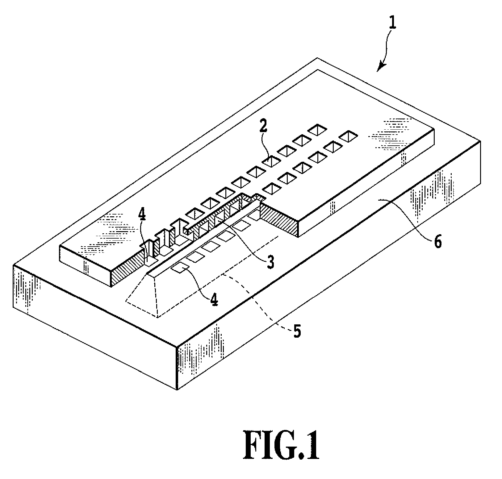
[0020]FIG. 1 is a perspective view showing an ink jet print head of this embodiment. On a silicon substrate 6 of the ink jet print head 1 there are provided a plurality of ejection openings 2, liquid paths 3, heaters 4 as an energy-generating elements that generate energy for discharging ink and an ink supply port 5. Ink is supplied from the ink supply port 5 to the liquid paths 3 and is boiled by the action of a thermal energy generated by the heater 4 provided in each liquid path 3. The ink, when boiled, is ejected from the ejection openings 2.

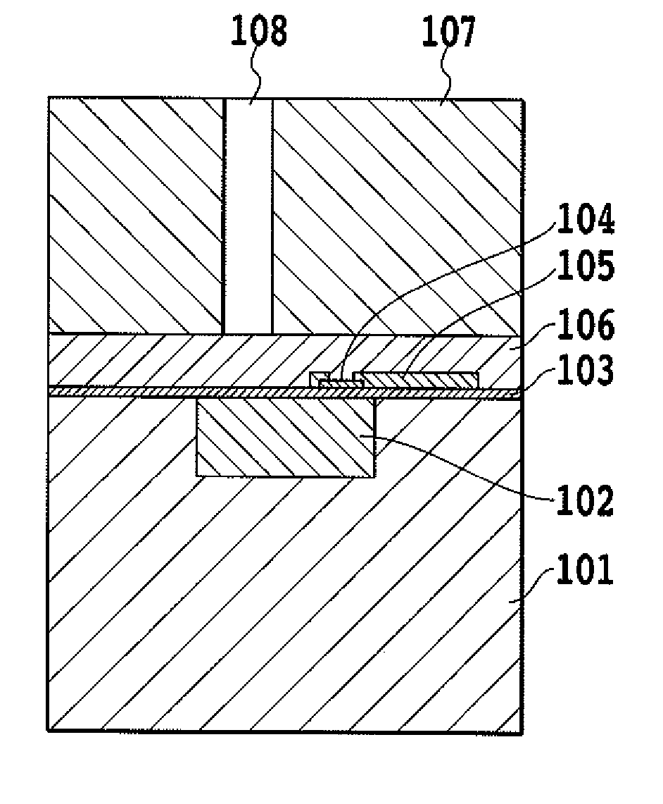
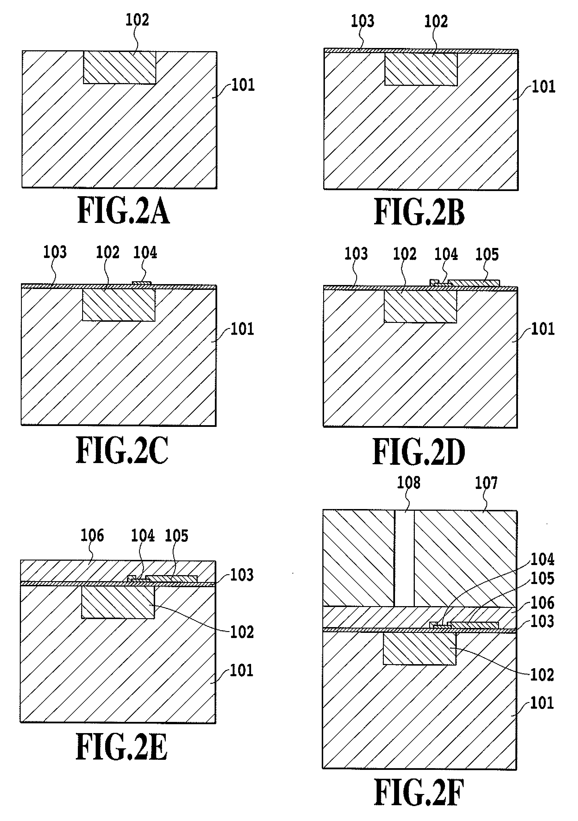
[0021]FIGS. 2A to 2F show a method of manufacturing the ink jet print head according to the first embodiment of this invention, showing a series of steps to form ejection openings in the silicon substrate.

[0022] First, by using a method disclosed in Japanese Patent Laid-Open No. 5-090113 (1993), a porous silicon area is formed in a portion of the silicon substrate 101 (625 μm thick, for example) where the liquid paths are ...


PUM

PropertyMeasurementUnit
Thicknessaaaaaaaaaa
Corrosion propertiesaaaaaaaaaa
Energyaaaaaaaaaa

Abstract

A method of manufacturing a liquid ejection head and a liquid ejection head capable of preventing corrosion of electrodes are provided. A method of manufacturing a liquid ejection head includes: a steps of forming porous silicon areas in portions of a silicon substrate where the liquid paths are to be formed; a steps of forming in layers in the porous silicon areas a protective layer, a heating resistor layer, an electrode layer and a heat accumulation layer; a steps of forming ink ejection openings in the silicon substrate; and a steps of removing the porous silicon areas.

Description

BACKGROUND OF THE INVENTION [0001] 1. Field of the Invention [0002] The present invention relates to a method of manufacturing a liquid ejection head and a liquid ejection head and more particularly to a method of manufacturing an ink jet print head and an ink jet print head. [0003] 2. Description of the Related Art [0004] A liquid ejection head, for example, an ink jet print head used in an ink jet printing apparatus is known to form ink droplets and eject them by a variety of methods. [0005] As one example use of the ink jet print head (also referred to simply as a print head), Japanese Patent Laid-Open No. 54-051837 (1979) discloses an ink jet printing method that applies thermal energy to the liquid to produce a force for liquid ejection. This printing method heats the liquid by the thermal energy to produce a bubble which in turn forces an ink droplet out of an orifice at the front end of the print head, sending the droplet flying onto a print medium to form an image. This type...

Claims


Application Information

Patent Timeline
IPC IPC(8): H01L21/00B41J2/04
CPCB41J2/1603B41J2/1628B41J2/1629Y10T29/4913B41J2/1642Y10T29/49128Y10T29/49401B41J2/1631
Inventor KOMURO, HIROKAZUKUROTOBI, MAKOTOATOJI, TADASHIOKABE, TAKEHITO
Owner CANON KK
Why Eureka
Try Eureka