
System and method of controlling automatic transmission

a technology of automatic transmission and transmission system, which is applied in the direction of transportation and packaging, instruments, etc., can solve the problems of brake slippage, delay in supply of working oil to the brake, and increase in the amount of working oil required for engaging the brake, so as to increase the torque capacity of the brake, and transmit a large torque

Active Publication Date: 2008-03-27
JATCO LTD +1
View PDF3 Cites 22 Cited by
  • Summary
  • Abstract
  • Description
  • Claims
  • Application Information

AI Technical Summary

Benefits of technology

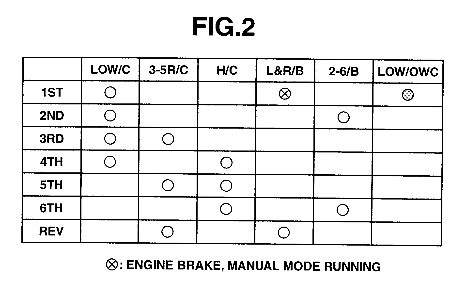
[0004]The brake disposed parallel to the roller one-way clutch is a friction element that is engaged when engine brake at low gear stage is applied, and during manual mode running and rearward running. Therefore, a torque capacity of the brake must be increased so as to transmit a large torque. Two manners of increasing the torque capacity of the brake are: (1) increasing the number of friction plates which form the brake; and (2) increasing an area of a cross section of a piston that presses against the friction plates, i.e., an area of a pressure-applying surface of a piston chamber to which a pressure is applied. The former of the two manners causes an increase in axial length of the transmission, and therefore, there is a tendency of adopting the latter of the two manners.
[0007]The present invention has been made in view of the above-described problems. It is an object of the present invention to provide a system and method of controlling an automatic transmission which is capable of improving starting and drivability of the vehicle under a condition of low temperatures of a working oil in the automatic transmission.

Problems solved by technology

However, if the torque capacity of the brake is increased in the latter of the two manners, there will occur an increase in the amount of the working oil which is required for engaging the brake.
Therefore, when a temperature of the working oil is too low to allow the one-way clutch to be engaged, supply of the working oil to the brake is delayed due to deterioration in flowability of the working oil.
This causes slippage in the brake.
Thus, in the conventional art as described above, failure upon starting of the vehicle would be still unavoidable.
Further, the above-described problem will occur not only at the start of the vehicle but also when a changeover from the gear stage other than the lowest gear stage to the lowest gear stage has attempted during the vehicle running at a low temperature of the working oil.
In this case, a motive power from the engine cannot be transmitted so that the driving force demanded by the vehicle driver cannot be obtained.

Method used


Image

  • System and method of controlling automatic transmission
  • System and method of controlling automatic transmission
  • System and method of controlling automatic transmission

Examples


Embodiment Construction

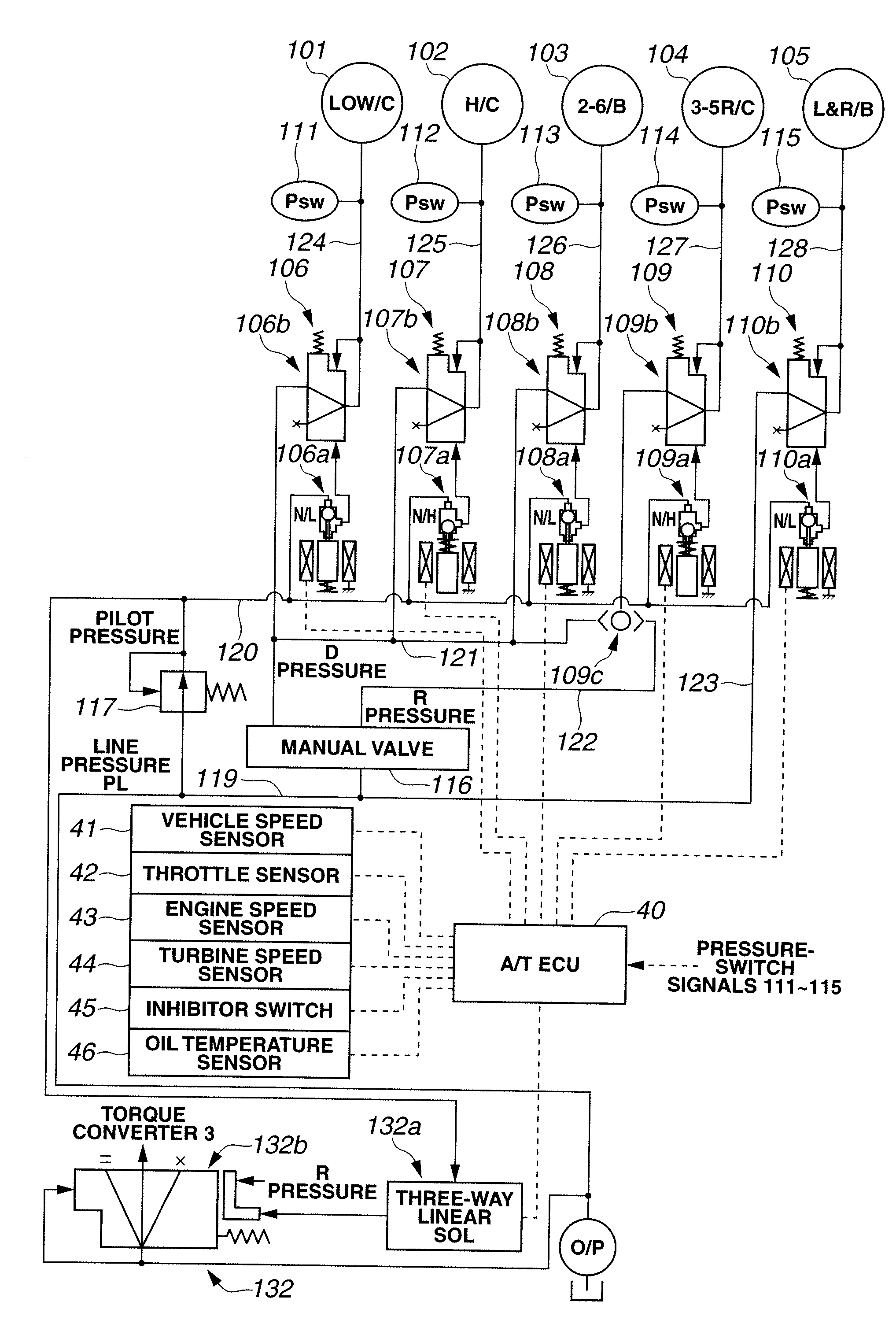
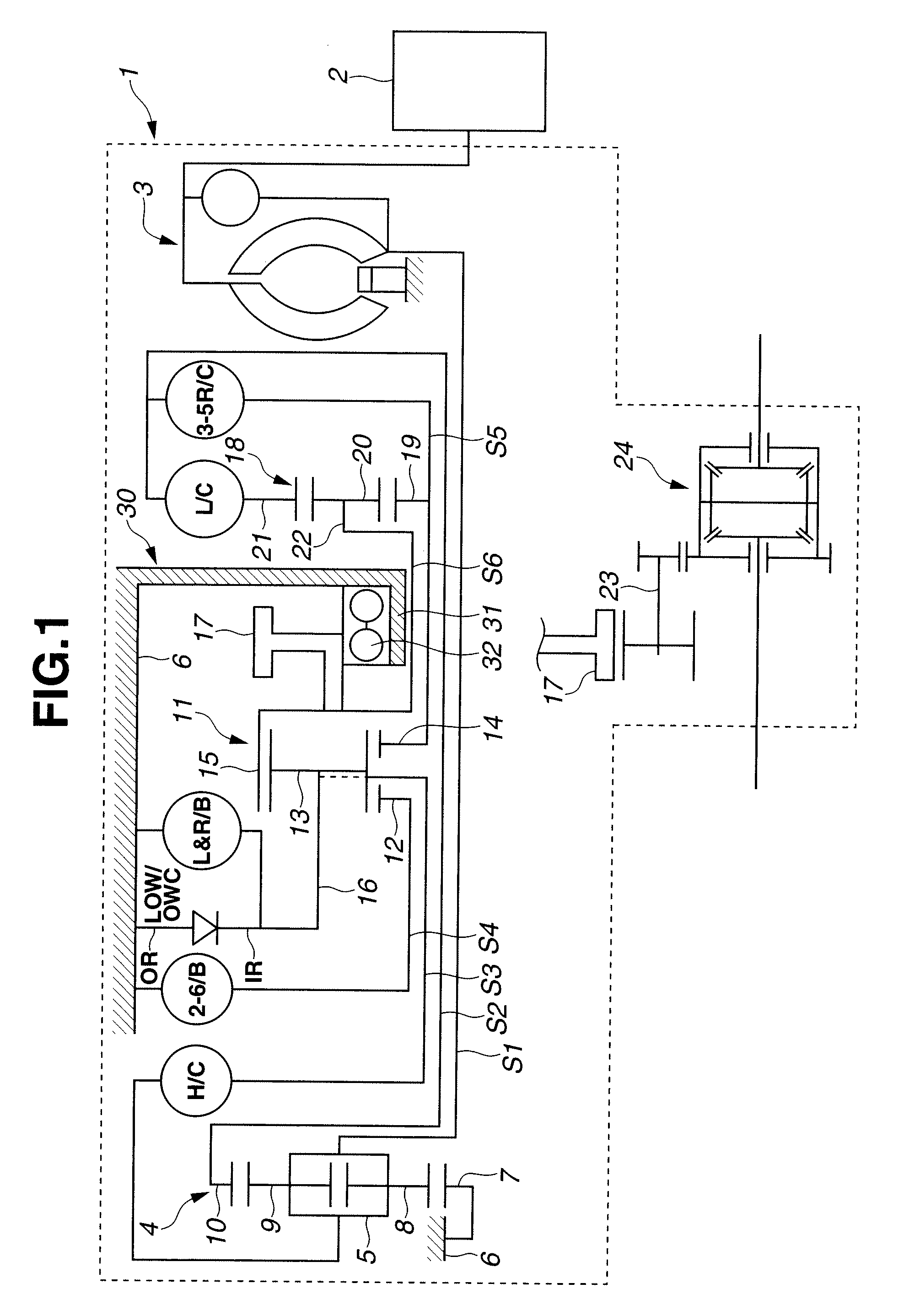
[0028]Referring to FIGS. 1-8, an embodiment of a system and method for controlling an automatic transmission, according to the present invention is explained. FIG. 1 is a skeleton diagram showing a gear train of the automatic transmission to which the system and method of the embodiment is applicable. The gear train has six forward gears and one reverse gear.

[0029]As shown in FIG. 1, automatic transmission 1 includes torque converter 3 that is coupled to engine 2. A motive power of engine 2 is inputted to torque converter 3 and then to carrier 5 of double-pinion planetary gearset 4 via rotation shaft S1. Double-pinion planetary gearset 4 includes sun gear 7 fixed to transmission casing 6, inner pinion 8 meshing with sun gear 7, outer pinion 9 meshing with inner pinion 8, ring gear 10 meshing with outer pinion 9 and disposed coaxially with sun gear 7, and carrier 5 supporting inner pinion 8 and outer pinion 9. Ring gear 10 is coupled to rotation shaft S2 that extends over an outer ci...


PUM


Abstract

In system and method of controlling an automatic transmission that includes a lowest gear-stage friction element and has a lowest gear stage having a largest gear ratio and a gear stage other than the lowest gear stage, the lowest gear stage being established through engagement of the lowest gear-stage friction element, the gear stage other than the lowest gear stage being established while the lowest gear-stage friction element is kept in disengagement, a temperature of working oil in the automatic transmission is sensed, and use of the lowest gear stage is inhibited and use of the gear stage other than the lowest gear stage is allowed when the sensed temperature of the working oil is lower than a first predetermined temperature as a predetermined extremely low temperature at which an engagement failure of the lowest gear-stage friction element is caused.

Description

BACKGROUND OF THE INVENTION[0001]The present invention relates to a system and method of controlling an automatic transmission under a low temperature condition of a working oil in the automatic transmission.[0002]A conventional multiple-speed automatic transmission includes a planetary gear set and a plurality of friction elements such as a clutch and a brake and performs a plurality of gear speeds by changing a combination of engagement and disengagement of the friction elements. For instance, there has been proposed an automatic transmission capable of performing a lowest gear stage which has a largest gear ratio by engaging a one-way clutch. However, if the one-way clutch is a roller one-way clutch, a vehicle could not be started even when a select lever is shifted from neutral “N” position or reverse “R” position to drive “D” position under a condition that a temperature of a working oil in the automatic transmission is low. This is because when the working oil temperature is l...

Claims


Application Information

Patent Timeline
IPC IPC(8): F16H59/00F16H61/18G06F17/00F16H59/08F16H59/72F16H61/12F16H61/16F16H61/68F16H61/684F16H61/686
CPCF16H3/666F16H59/72F16H61/12F16H61/686F16H2061/023F16H2061/1224Y10T477/653F16H2200/201F16H2200/2043F16H2312/02F16H2061/1272Y10T477/6934F16H2200/0052F16H61/04
Inventor WATANABE, TOMOHARUMICHIOKA, HIROFUMIOTAKE, KAZUNARI
Owner JATCO LTD
Learn More