Engine controller

Active Publication Date: 2008-03-27
MITSUBISHI ELECTRIC CORP
View PDF2 Cites 9 Cited by
  • Summary
  • Abstract
  • Description
  • Claims
  • Application Information

AI Technical Summary

Benefits of technology

[0020]In accordance with the engine controller in this invention, the existence of sky short circuit, ground and disconnection abnormalities can be reliably judged by individually judging abnormalities of wiring of the positive terminal side and wiring of the negative terminal side of the exhaust gas sensor. Further, even

Problems solved by technology

Further, it is detected as a ground abnormality at a disconnection abnormality time of the signal line by connecting a pull-down resistor to the positive signal line.
However, a ground abnormal

Method used


Image

  • Engine controller
  • Engine controller
  • Engine controller

Examples


embodiment mode 1

of the Invention

(1) Detailed Explanation of Construction

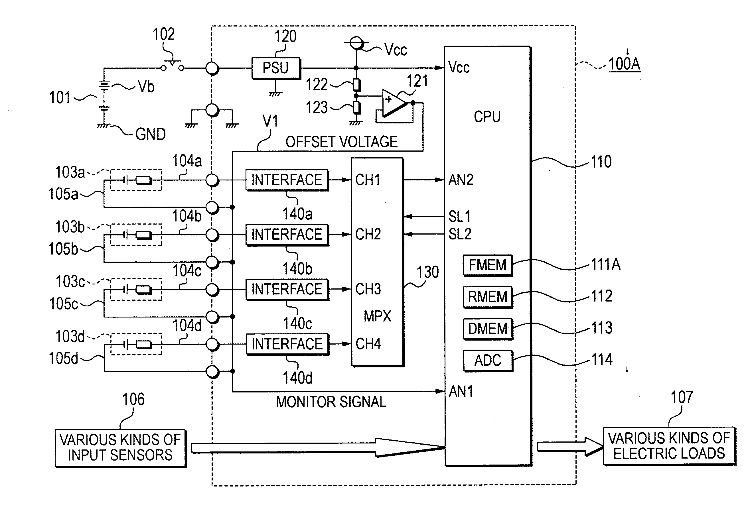
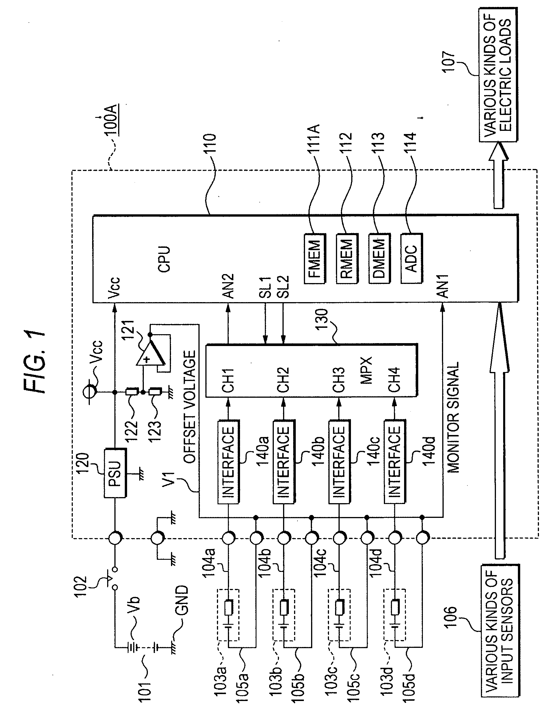
[0034]FIG. 1 showing a circuit block diagram of a first embodiment device of this invention will next be explained. In FIG. 1, a vehicle mounting battery 101 is connected between a positive side electricity supply terminal and a negative side electricity supply terminal of an engine controller 100A through an output contact 102 of an electric power source relay.

[0035]The output contact 102 is immediately closed when an unillustrated electric power source switch is closed. However, even when the electric power source switch is opened, a delay returning operation for continuing electric supply to the engine controller 100A for a predetermined delay time is performed.

[0036]Plural exhaust gas sensors 103a to 103d are arranged in the exterior of the engine controller 100A. Positive terminals of the respective exhaust gas sensors are connected to the engine controller 100A by positive wirings 104a to 104d. Negative terminals of the r...

embodiment mode 2

of the Invention

(1) Detailed Explanation of Construction

[0105]FIG. 6 showing a circuit block diagram of a second embodiment device of this invention will next be explained with points different from those of FIG. 1 as a center. FIG. 6 differs from FIG. 1 in a method of negative line wiring of exhaust gas sensors 103a to 103d, and addition of a negative line disconnection abnormality detecting means is a main different point. The same or corresponding portions are designated by the same reference numerals as FIG. 1.

[0106]In FIG. 6, similar to FIG. 1, a vehicle mounting battery 101, an output contact 102 of an electric power source relay, various kinds of input sensors 106 and various kinds of electric loads 107 are connected to an engine controller 100B. Further, positive terminals of plural exhaust gas sensors 103a to 103d are connected to the engine controller 100B by positive wirings 104a to 104d.

[0107]A negative terminal of the exhaust gas sensor 103a is connected to the engine ...

embodiment mode 3

of the Invention

(1) Detailed Explanation of Construction

[0154]FIG. 9 showing a circuit block diagram of a third embodiment device of this invention will next be explained with points different from those of FIG. 1 as a center.

[0155]FIG. 9 differs from FIG. 1 in the contents of interface circuits with respect to exhaust gas sensors 103a to 103d, and addition of a sensor resistance measuring means for detecting a short circuit abnormality is a main different point. The same or corresponding portions are designated by the same reference numerals as FIG. 1.

[0156]In FIG. 9, similar to FIG. 1, a vehicle mounting battery 101, an output contact 102 of an electric power source relay, plural exhaust gas sensors 103a to 103d, various kinds of input sensors 106 and various kinds of electric loads 107 are connected to an engine controller 100C.

[0157]As the internal construction of the engine controller 100C, similar to FIG. 1, a microprocessor 110 is mutually bus-connected so as to be cooperated...


PUM


Abstract

Respective positive terminal electric potentials of exhaust gas sensors are sequentially selectively inputted to an analog input terminal of a multi-channel AD converter through a multiplexer. An offset voltage is applied to respective negative terminals of the exhaust gas sensors. This offset voltage is inputted to another input terminal of the multi-channel AD converter. A microprocessor detects a generating voltage of the exhaust gas sensors by the difference between a digital converting value of the positive terminal electric potential and a digital converting value of the negative terminal electric potential. The microprocessor also individually judges that each of the digital converting values is excessively small and excessively large. Thus, the microprocessor judges the existence of ground, sky short circuit and disconnection abnormalities of the negative terminal and the positive terminal.

Description

BACKGROUND OF THE INVENTION[0001]1. Field of the Invention[0002]This invention relates to an engine controller for feeding-back and controlling an air fuel ratio of an internal combustion engine, and particularly relates to an improvement of an abnormality diagnosing device built-in and used in the engine controller, and detecting a breakdown and a wiring abnormality of an exhaust gas sensor externally connected to detect the air fuel ratio and annunciating the abnormality.[0003]2. Background Art[0004]The exhaust gas sensor called a lambda type as a popular name to feed-back and control the air fuel ratio of the internal combustion engine, is widely practically used. For example, this lambda type exhaust gas sensor is arranged before and after a catalyst arranged in an exhaust pipe path, and generates a detecting voltage Vs according to oxygen concentration within exhaust gas. This detecting voltage Vs is about 0.45 V in a theoretical air fuel ratio as a driving target. However, thi...

Claims


Application Information

Patent Timeline
IPC IPC(8): F02D28/00F02D45/00G01M15/10
CPCF01N2560/02F02D41/1454F02D41/222Y02T10/40G01R31/025G01R31/2829G01R31/007G01R31/52
Inventor ZUSHI, YUJITANAKA, TORUYOKONO, MICHIHISAFUKUI, AKIHIROMATSUDA, YUSUKE
Owner MITSUBISHI ELECTRIC CORP
Why Eureka
Try Eureka