Aircraft fuel pipe coupling

a fuel pipe and aircraft technology, applied in the direction of electrically conductive connections, pipe elements, non-rotary current collectors, etc., can solve the problems of fuel carrying by the fuel pipe igniting, aircraft fuel system of static electricity build-up on one pipe, and heavy prior art arrangemen

Inactive Publication Date: 2008-04-03
AIRBUS OPERATIONS LTD
View PDF46 Cites 40 Cited by
  • Summary
  • Abstract
  • Description
  • Claims
  • Application Information

AI Technical Summary

Benefits of technology

[0014]The resiliently flexible electrical contact may be removable from the coupling. Advantageously, this would

Problems solved by technology

There is a danger in aircraft fuel systems of a build up of static electricity on one pipe in comparison to another pipe to which it is connected.
This may cause an electrical discharge or spark which could result in the fuel carried by the fuel pip

Method used


Image

  • Aircraft fuel pipe coupling
  • Aircraft fuel pipe coupling
  • Aircraft fuel pipe coupling

Examples


first embodiment

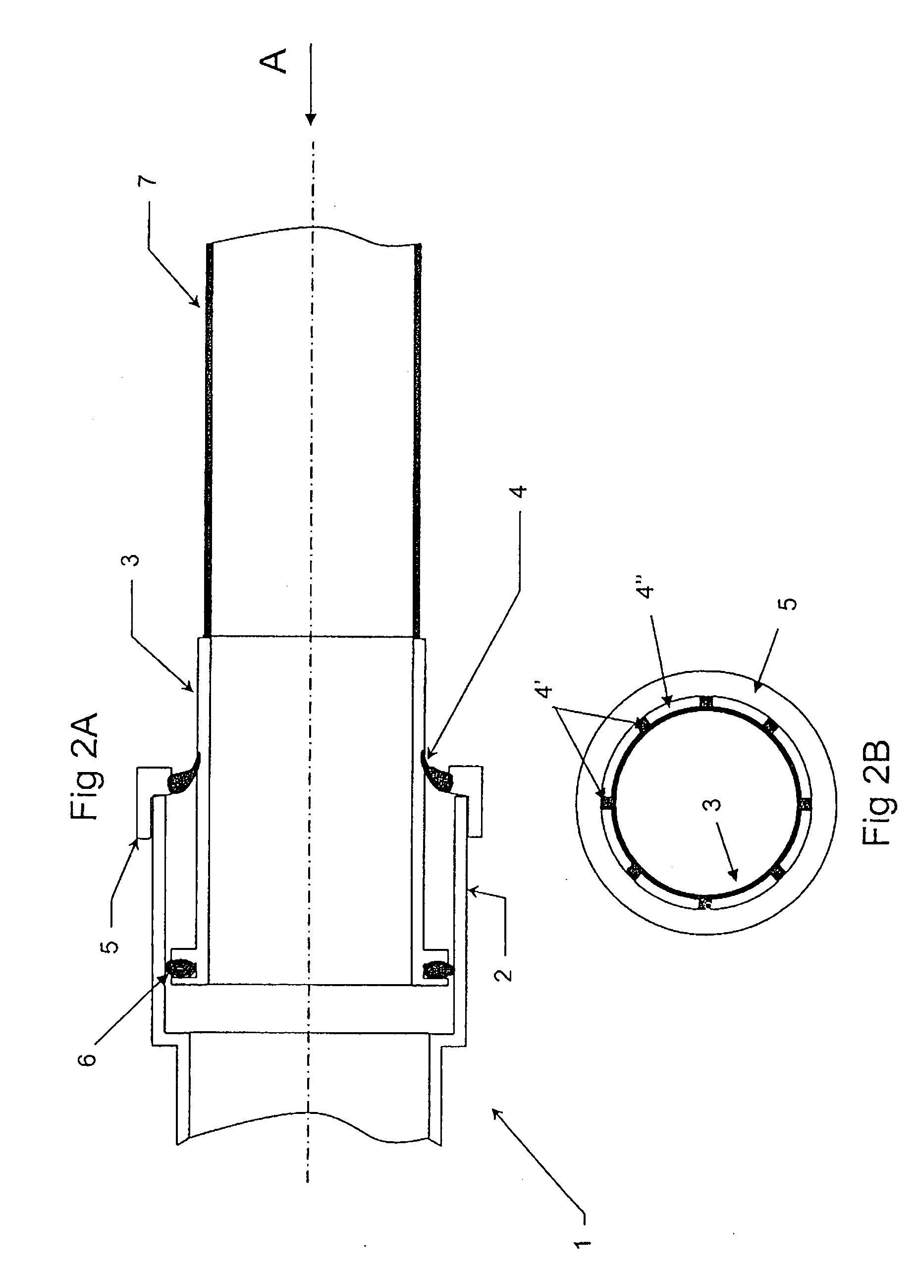
[0030]FIG. 2A shows the invention including a fuel pipe coupling 1 comprising a socket 2, a pipe end fitting 3, a resiliently flexible electrically conductive lip 4, a nut 5, an O-ring seal 6, and a fuel pipe 7. The pipe end fitting 3 is located within the socket 2 and includes the seal 6 between the male outer surface of the pipe end fitting 3 and the female inner surface of the socket 2. The nut 5 is fitted (for example by welding) to the end of the socket 2. The conductive lip 4 is attached to the nut 5 and protrudes from the nut such that it contacts the pipe end fitting 3. The coupling connects fuel pipes of an aircraft fuel system.

[0031]FIG. 2B is a view of the connector 1 from the direction of arrow A in FIG. 2A. It shows the pipe end fitting 3, the nut 5 and the conductive lip 4. The conductive lip 4 is made up of a plurality of metallic wires 4′ embedded into a elastomeric material 4″. As is clearly shown, the metallic wires 4′ provide an electrical contact between the nut ...

second embodiment

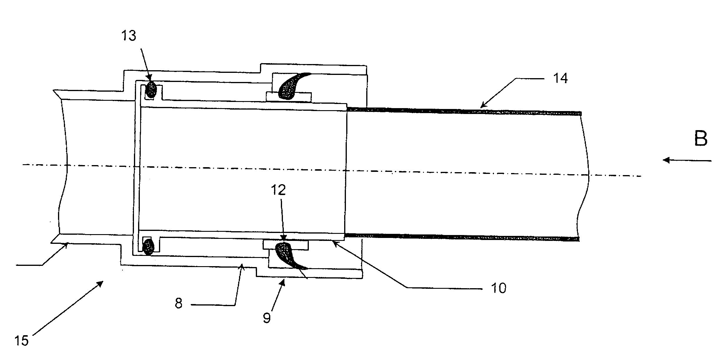
[0034]FIG. 3A shows the invention including a fuel pipe coupling 15 comprising a socket 8, the socket including an extended section 9 with a wider radius than that of the main part of the socket, a pipe end fitting 10, a plurality of metallic brushes 11, a flange 12, an O-ring seal 13, and a pipe 14. The pipe end fitting 10 is located within the socket 8 and includes the seal 13 between the male outer surface of the pipe end fitting 10 and the female inner surface of the socket 8. The flange 12 is welded to the pipe end fitting 10. The plurality of metallic brushes 11 are attached to the flange 12, both the flange 12 and the brushes 11 situated such that they are within the extended section 9 of the socket 8. The brushes 11 extend from the flange 12 such that they contact the extended section 9 of the socket 8.

[0035]FIG. 3B is a view of the connector 15 from the direction of arrow B in FIG. 3A. It shows the pipe end fitting 10, the flange 12, the metallic brushes 11 and the socket 8...


PUM


Abstract

A coupling for connecting fuel pipes in an aircraft is provided. At least one of the fuel pipes is capable of movement with respect to the coupling. The coupling comprises a pipe end fitting and a socket arrangement. The pipe end fitting is located within the socket arrangement. At least one resiliently flexible electrical contact is located between the pipe end fitting and the socket arrangement. The coupling may thus form a flexible coupling electrically connecting two pipes to prevent static electricity build-up whilst permitting movement between the pipes.

Description

TECHNICAL FIELD[0001]The present invention relates to aircraft fuel pipe couplings and in particular but not exclusively flexible fuel pipe couplings for connecting a fuel pipe in an aircraft fuel system to another fuel pipe.BACKGROUND OF THE INVENTION[0002]There is a danger in aircraft fuel systems of a build up of static electricity on one pipe in comparison to another pipe to which it is connected. This may cause an electrical discharge or spark which could result in the fuel carried by the fuel pipes igniting. In the prior art, fuel couplings include a wire bonded to each side of a coupling in order to electrically connect them and prevent static build up on parts of the connector. The wire is bonded to lugs present on the coupling and as a further safety feature there may be one or more back up wires and corresponding lugs. The arrangement of the prior art is both heavy and complex. The position of the connection externally to the coupling also leaves it vulnerable to damage. F...

Claims


Application Information

Patent Timeline
IPC IPC(8): B64D37/00F16L21/00H01R4/60
CPCF16L21/03F16L25/01F16L27/026F16L27/125B64D45/02H01R41/00B64D37/005B64D37/32H01R4/643
Inventor PETIT, DAVID PATRICK
Owner AIRBUS OPERATIONS LTD
Why Eureka
Try Eureka