RF transceiver with undesired signal rejection and methods for use therewith

a transceiver and undesired technology, applied in the field of wireless communication systems, can solve the problems of reducing the magnitude of the desired channel(s) by about 3 db, affecting the ability of the receiver to accurately recover data, and expensive parts

Inactive Publication Date: 2008-04-03
AVAGO TECH INT SALES PTE LTD
View PDF1 Cites 10 Cited by
  • Summary
  • Abstract
  • Description
  • Claims
  • Application Information

AI Technical Summary

Problems solved by technology

For example, in a cellular system, it is fairly common to have significant nearby interferers of the frequency band of interest (e.g., one or more desired channel(s) of 5-60 MHz centered at a frequency of about 900 MHz, 1800 MHz, 1900 MHz, and / or 2100 MHz) that adversely affect the ability of a receiver to accurately recover data.
However, with nearby interferers (e.g., within 100 MHz), the BPF needs a steep roll off to sufficiently attenuate the interferers making it an expensive part.
In addition, an off-chip BPF typically reduces the magnitude of the desired channel(s) by about 3 dB.
While this reduces the cost and the attenuation of the desired channel(s), it does not sufficiently attenuate large nearby interferers.

Method used


Image

  • RF transceiver with undesired signal rejection and methods for use therewith
  • RF transceiver with undesired signal rejection and methods for use therewith
  • RF transceiver with undesired signal rejection and methods for use therewith

Examples


Embodiment Construction

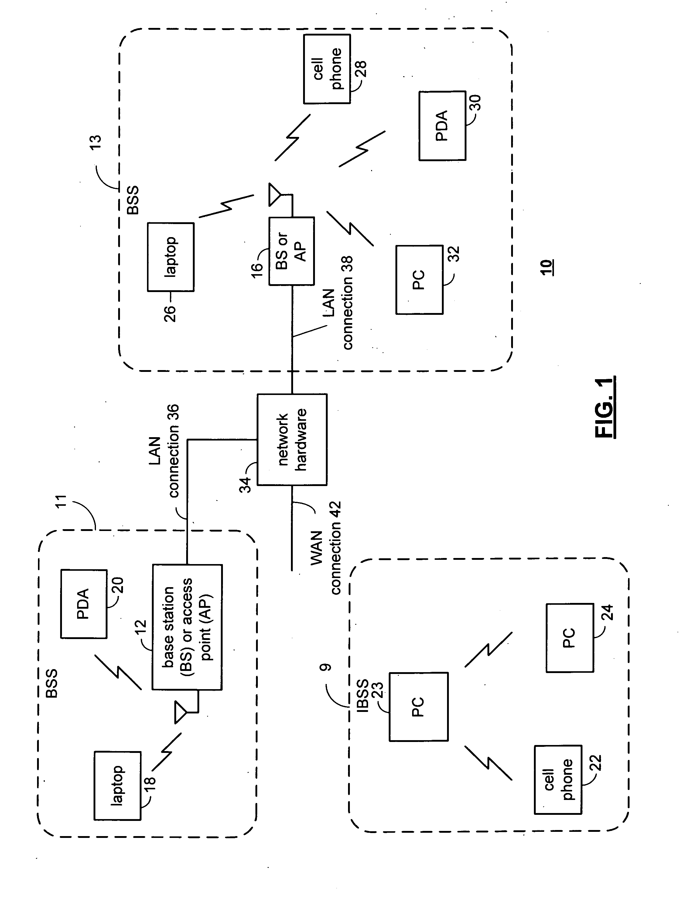
[0022]FIG. 1 is a schematic block diagram illustrating a communication system 10 that includes a plurality of base stations and / or access points 12, 16, a plurality of wireless communication devices 18-32 and a network hardware component 34. Note that the network hardware 34, which may be a router, switch, bridge, modem, system controller, et cetera provides a wide area network connection 42 for the communication system 10. Further note that the wireless communication devices 18-32 may be laptop host computers 18 and 26, personal digital assistant hosts 20 and 30, personal computer hosts 24 and 32 and / or cellular telephone hosts 22 and 28 that include a wireless transceiver. The details of the wireless transceiver will be described in greater detail with reference to FIGS. 3-7.

[0023]Wireless communication devices 22, 23, and 24 are located within an independent basic service set (IBSS) area and communicate directly (i.e., point to point). In this configuration, these devices 22, 23,...


PUM


Abstract

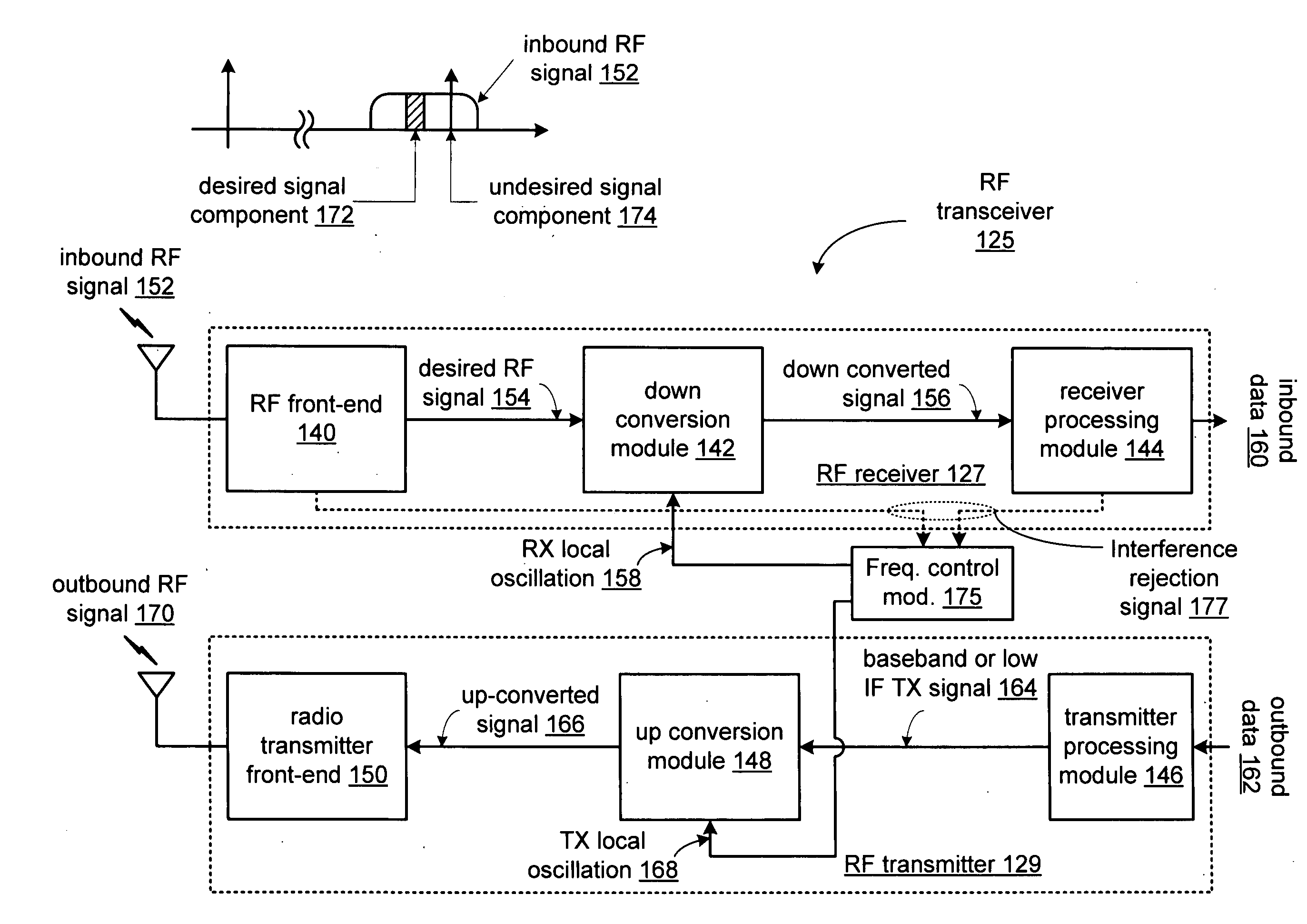
A radio frequency (RF) transceiver includes an RF transmitter that generates an outbound RF signal at a carrier frequency that is based on a transmitter local oscillation. An RF front-end receives an inbound RF signal that includes a desired signal component that is based on the outbound RF signal and that includes an undesired signal component. The RF front-end includes a first RF combiner module that attenuates the undesired signal component to produce a desired RF signal. A down conversion module generates a down converted signal from the desired RF signal based on a receiver local oscillation. A receiver processing module generates inbound data from the down converted signal. A frequency control module controls a frequency of the transmitter local oscillation and a frequency of the receiver local oscillation, based on an interference rejection signal, to control the attenuation of the undesired signal component.

Description

BACKGROUND OF THE INVENTION[0001]1. Technical Field of the Invention[0002]This invention relates generally to wireless communications systems and more particularly to radio transceivers used within such wireless communication systems that include RF tags.[0003]2. Description of Related Art[0004]Communication systems are known to support wireless and wire line communications between wireless and / or wire line communication devices. Such communication systems range from national and / or international cellular telephone systems to the Internet to point-to-point in-home wireless networks. Each type of communication system is constructed, and hence operates, in accordance with one or more communication standards. For instance, wireless communication systems may operate in accordance with one or more standards including, but not limited to, IEEE 802.11, Bluetooth, advanced mobile phone services (AMPS), digital AMPS, global system for mobile communications (GSM), code division multiple acces...

Claims


Application Information

Patent Timeline
Patent Type & Authority Applications(United States)
IPC IPC(8): H04Q5/22
CPCH04B1/14
Inventor ROFOUGARAN AHMADREZA (REZA)
Owner AVAGO TECH INT SALES PTE LTD
Why Eureka
Try Eureka