Electrode Catalyst For Fuel Cell, Electrode For Fuel Cell, And Fuel Cell

a fuel cell and electrode technology, applied in the direction of organic compounds/hydrides/coordination complex catalysts, cell components, physical/chemical process catalysts, etc., can solve the problems of increasing the amount of information dealt with electronic instruments such as personal computers, increasing the electric power consumption of such instruments, and increasing the electric power consumption. , to achieve the effect of enhancing the utilization efficiency of catalysts, enhancing the current-voltage characteristics, and enhancing the electrical conductivity

Inactive Publication Date: 2008-04-03
KONICA MINOLTA INC
View PDF4 Cites 5 Cited by
  • Summary
  • Abstract
  • Description
  • Claims
  • Application Information

AI Technical Summary

Benefits of technology

[0031] According to the invention, there was provided an electrode catalyst for use in fuel cells, achieving enhance utilization efficiency of the catalyst and an electrode for fuel cells was prepared by use of the catalyst, whereby there was provided a fuel cell exhibiting superior current-voltage characteristics.
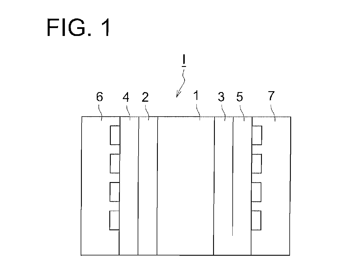
[0032]FIG. 1 illustrates an example of a unit cell of a fuel cell of the invention.
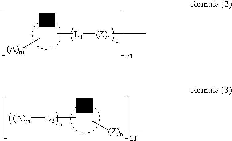
[0039] One aspect of the invention is that the electrode catalyst for fuel cells is a metal catalyst onto which is adsorbed a compound having at least one functional group comprising a sulfur element or a nitrogen element as a part or all of constituent atoms and at least one proton-accepting group in the molecule. The compound having at least one functional group comprising a sulfur element or a nitrogen element as a part or all of constituent atoms and at least one proton-accepting group in the molecule is preferably a compound represented by formulas (1) to (5), as described above.
[0040] The invention will be further described below.
[0041] In the formulas (1) to (5), examples of a functional group represented by Z, comprising a sulfur element as a part or all of constituent atoms include a group comprised of a sulfur element and other elements, e.g., a mercapto group, a sulfon group, a sulfide group such as a monosulfide group, a disulfide group or a trisulfide group (in which the sulfur straight chain group may form a sulfur straight chain derivative such as methylthiobenzyl, naphthyltrithiopropyl, or benzothiazolyldithiobutyl); and a cyclic group such as a carbocyclic or heterocyclic group which is substituted by a group comprised of a sulfur element, e.g., mercaptophenyl, thioureidophenyl, phenyldithiobenzothiazolyl, 2-mercaptoimidazolyl, 2-mercaptopyrimidinyl, mercaptotetrazolyl, mercaptotriazolyl, mercaptothiazolyl, 1(2H)-2-thioxopyridyl, 5-mercaptothienyl, 4-thioureidophenyl and 2-thioacetylpyridyl.
[0058] A wide variety of additives may be added to the catalyst layer. Such additives include, for example, a conductive agent to enhance electric conductivity, such as carbon, a polymer binder to enhance binding ability and a water repellency agent to enhance water repellency. Specific examples of a water repellency agent include fluororesins such as polytetrafluoroethylene (PTFE), e.g., Teflon (trade name), tetrafluoroethylene-perfluoroalkylvinyl ether copolymer and tetrafluoroethylene-hexafluoropropylene copolymer.

Problems solved by technology

Recently, the amount of information dealt with electronic instruments such as personal computers increased dramatically along with the dawn of information-oriented society and electric power consumption of such instruments has markedly increased.
Specifically in portable electronic instruments, this increase of electric power consumption has become a major problem for an increased processing capability.
Presently in such portable electronic instruments, a lithium battery is generally used as the power supply but energy density of lithium batteries has been pushed to its limit.
One reason for this problem is that the catalyst surface causing the decomposition reaction is not close enough to the migration route of produced protons.
In conventional methods of preparing a catalyst layer, however, the proportion of a polymer electrolyte existing around the platinum catalyst is relatively small, which renders it difficult to achieve prompt material transfer.
However, the foregoing techniques do not always produce a proton migration route close enough to the vicinity of a catalyst, resulting in little gain in enhancement of efficiency.

Method used


Image

  • Electrode Catalyst For Fuel Cell, Electrode For Fuel Cell, And Fuel Cell
  • Electrode Catalyst For Fuel Cell, Electrode For Fuel Cell, And Fuel Cell
  • Electrode Catalyst For Fuel Cell, Electrode For Fuel Cell, And Fuel Cell

Examples


examples

[0070] The present invention will be further described with reference to examples but are by no means limited to these.

Preparation of Catalyst

Preparation of Catalyst 1:

Adsorption of Particulate Gold to Platinum Black and Reduction

[0071] 0.5 g of platinum ruthenium black (TEC 090110, produced by Tanaka Kikinzoku Co., Ltd.) was mixed with 1000 ml of pure water. Then, 40 ml of an aqueous 1 mol / L chloroauric acid solution was added thereto. An aqueous 2 mol / L sodium citrate solution was further added so as to make a concentration of 100 mmol as a reducing agent. This solution was stirred at 95° C. for 7 hrs. Thereafter, filtration and drying were conducted to obtain platinum deposited on platinum ruthenium black.

Preparation of Catalyst 2:

Adsorption of Particulate Gold onto Platinum Ruthenium Bearing Carbon and Reduction

[0072] Platinum ruthenium bearing carbon catalyst (TEC 81E81, produced by Tanaka Kikinzoku Co., Ltd.) was mixed at an amount of 0.5 g, based on platinum with 1...


PUM

PropertyMeasurementUnit
molecular lengthaaaaaaaaaa
porosityaaaaaaaaaa
temperatureaaaaaaaaaa

Abstract

Disclosed is an electrode catalyst for fuel cells, achieving enhanced utilization efficiency of the catalyst. Also disclosed are an electrode for fuel cells by use of the catalyst and a fuel cell. The electrode catalyst for fuel cells is featured in that a compound having at least one functional group and at least one proton-accepting group in the molecule is adsorbed onto a metal catalyst, and the functional group being partially or wholly constituted of a sulfur element or a nitrogen element as its constituent atoms.

Description

TECHNICAL FIELD [0001] The present invention relates to an electrode catalyst for use in fuel cells, an electrode used for fuel cells and a fuel cell. TECHNICAL BACKGROUND [0002] Recently, the amount of information dealt with electronic instruments such as personal computers increased dramatically along with the dawn of information-oriented society and electric power consumption of such instruments has markedly increased. Specifically in portable electronic instruments, this increase of electric power consumption has become a major problem for an increased processing capability. Presently in such portable electronic instruments, a lithium battery is generally used as the power supply but energy density of lithium batteries has been pushed to its limit. [0003] In such situations, instead of lithium batteries, the period of continuous use of a portable electronic instrument is expected to be greatly enhanced by the use of fuel cells exhibiting a higher energy density and an enhanced h...

Claims


Application Information

Patent Timeline
Patent Type & Authority Applications(United States)
IPC IPC(8): B01J31/02B01J27/02B01J27/14B01J27/24
CPCH01M4/90H01M4/92Y02E60/50H01M2008/1095H01M4/923
Inventor CHIBA, TAKATOSUZUKI, TAKAYUKI
Owner KONICA MINOLTA INC
Why Eureka
Try Eureka