Rotatable cutting tool and cutting tool body

a cutting tool and rotatable technology, applied in the direction of cutting machines, slitting machines, earthwork drilling and mining, etc., can solve the problems of premature failure of the cutting tool body, severe wear and severe stress and the termination of the useful life of the rotatable cutting tool

Active Publication Date: 2008-04-10
KENNAMETAL INC
View PDF13 Cites 27 Cited by
  • Summary
  • Abstract
  • Description
  • Claims
  • Application Information

AI Technical Summary

Benefits of technology

[0009]In one form thereof, the invention is an elongate rotatable cutting tool body with a central longitudinal axis. The tool body comprises an axial forward end and an axial rearward end. The cutting tool body also has a head portion, a shank portion and a collar portion wherein the collar portion is mediate of and contiguous with the head portion and the shank portion. The head portion is adjacent to the axial forward end, and the shank portion is adjacent to the axial rearward end. The cutting tool body has an axial forward hardness region beginning at and extending a first pre-selected distance in an axial rearward direction from the axial forward end to encompass the entire head portion and at least an axial forward section of the collar portion. The axial forward hardness region has a hardness equal to or greater than a first hardness, as well as a first average hardness. The cutting tool body has an axial rearward hardness region beginning at and extending a second pre-selected distance in an axial forward direction from the axial rearward end to encompass an axial rearward section of the shank portion. The axial rearward hardness region has a third average hardness. The cutting tool body also has a transition hardness region mediate of and contiguous with the axial forward hardness region and the axial rearward hardness region. The transition hardness region encompasses an axial rearward section of the collar portion and an axial forward section of the shank portion. The transition hardness region has a second average hardness. The second average hardness is less than the first hardness, and the third average hardness is less than the second average hardness.
[0010]In still another form thereof, the invention is a elongate rotatable cutting tool body having a central longitudinal axis. The cutting tool body comprises an axial forward end and an axial rearward end. The cutting tool body has an enlarged diameter collar mediate of the axial forward end and the axial rearward end wherein the mediate collar presents an axial forward facing surface and an axial rearward facing surface. The cutting tool body has an axial forward hardness region beginning at and extending a first pre-selected distance in an axial rearward direction from the axial forward end to encompass the axial forward facing surface of the collar. The axial forward hardness region has a hardness equal to or greater than a first hardness, as well as a first average hardness. The cutting tool body has an axial rearward hardness region beginning

Problems solved by technology

The severe operational environment subjects the components of the rotatable cutting tool to both severe abrasive wear and severe stress.
As one can appreciate, if a cutting tool body does not exhibit sufficient wear resistance and/or toughness, there exists the risk that the cutt

Method used


Image

  • Rotatable cutting tool and cutting tool body
  • Rotatable cutting tool and cutting tool body
  • Rotatable cutting tool and cutting tool body

Examples


Embodiment Construction

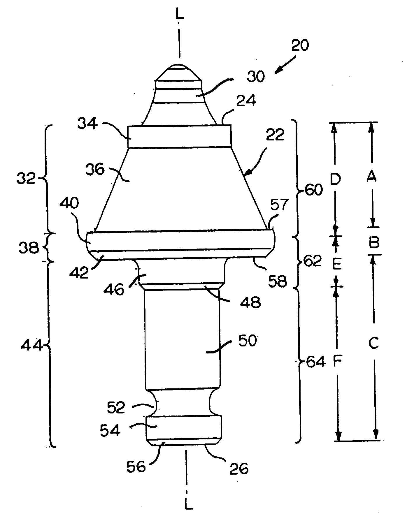
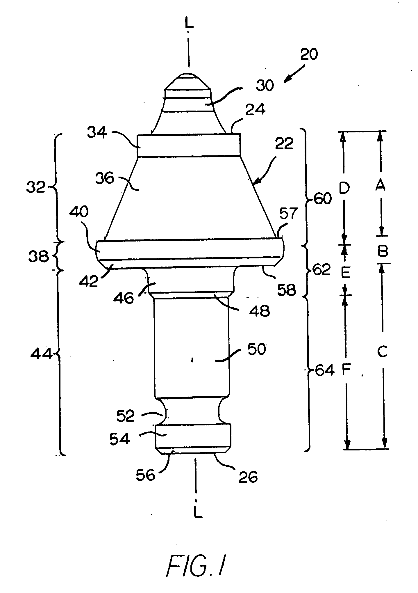
[0018]Referring to the drawings, FIG. 1 illustrates one specific embodiment of a rotatable cutting tool generally designated as 20. Rotatable cutting tool 20 comprises an elongate cutting tool body generally designated as 22. The cutting tool body 22 is typically made from steel such as those grades disclosed in U.S. Pat. No. 4,886,710 to Greenfield, which is hereby incorporated by reference herein. Grade 15B37H Modified is the preferred grade of steel for the cutting tool body 22. Grade 15B37H Modified has the following nominal composition (in weight percent): 0.33-0.38% carbon, 1.10-1.35% manganese, 0.0005% minimum boron, 0.15-0.30% silicon, 0.045% maximum sulfur, 0.035% maximum phosphorus and the balance iron. Grade 15B37H Modified has a minimum hardenability equal to about 52 HRc.

[0019]The cutting tool body 22 has an axial forward end 24 and an axial rearward end 26. A hard insert 30 is affixed (such as by brazing or the like) in a socket (not illustrated) in the axial forward e...


PUM


Abstract

A rotatable cutting tool carried in a bore of a holder wherein the holder has a forward surface surrounding a forward end of the bore. The rotatable cutting tool includes an elongate cutting tool body that has a central longitudinal axis, an axial forward end and an axial rearward end. The cutting tool body contains a socket in the axial forward end thereof whereby the socket receives a hard insert therein. The cutting tool body has an enlarged diameter collar mediate of the axial forward end and the axial rearward end. The mediate collar presents an axial forward facing surface and an axial rearward facing surface. The cutting tool body has an axial forward hardness region beginning at and extending a first pre-selected distance in an axial rearward direction from the axial forward end to encompass the axial forward facing surface of the collar. The axial forward hardness region has a hardness equal to or greater than a first hardness, as well as a first average hardness. The cutting tool body has an axial rearward hardness region beginning at and extending a second pre-selected distance in an axial forward direction from the axial rearward end to encompass an axial rearward section of the shank portion. The axial rearward hardness region has a third average hardness. The cutting tool body has a transition hardness region mediate of and contiguous with the axial forward hardness region and the axial rearward hardness region. The transition hardness region encompasses the axial rearward facing surface of the collar and an axial forward section of the shank portion. The transition hardness region has a second average hardness. The second average hardness is less than the first hardness, and the third average hardness is less than the second average hardness.

Description

BACKGROUND OF THE INVENTION[0001]The invention pertains to a rotatable cutting tool that is useful for the impingement of earth strata such as, for example, asphaltic roadway material, coal deposits, mineral formations and the like. More specifically, the present invention pertains to a rotatable cutting tool that is useful for the impingement of earth strata, and especially a cutting tool body that is a component of such a rotatable cutting tool. The cutting tool body exhibits improved hardness properties to thereby provide improved performance characteristics (e.g., wear resistance and toughness) for the entire rotatable cutting tool.[0002]Heretofore, rotatable cutting tools have been used to impinge earth strata such as, for example, asphaltic roadway material. U.S. Pat. No. 4,201,421 to Den Besten et al,. and U.S. Pat. No. 4,497,520 B2 to Ojanen are exemplary of rotatable cutting tools used to impinge earth strata, and especially asphaltic roadway material.[0003]Generally speaki...

Claims


Application Information

Patent Timeline
IPC IPC(8): E21C25/00
CPCE21C35/183
Inventor MARATHE, ANIRUDDHA S.OJANEN, RANDALL W.BITLER, JONATHAN W.MACLNTYRE, RAY C.
Owner KENNAMETAL INC
Why Eureka
Try Eureka