
Noise-attenuating laminate composite wallboard panel and methods for manufacturing same

a laminate composite wallboard and noise-attenuating technology, applied in the field of building materials, can solve the problems of using surface and section together without uniformity, and achieve the effects of superior noise attenuation, superior noise attenuation, and similar weigh

Inactive Publication Date: 2008-04-17
AVERILL RONALD C
View PDF7 Cites 12 Cited by
  • Summary
  • Abstract
  • Description
  • Claims
  • Application Information

AI Technical Summary

Benefits of technology

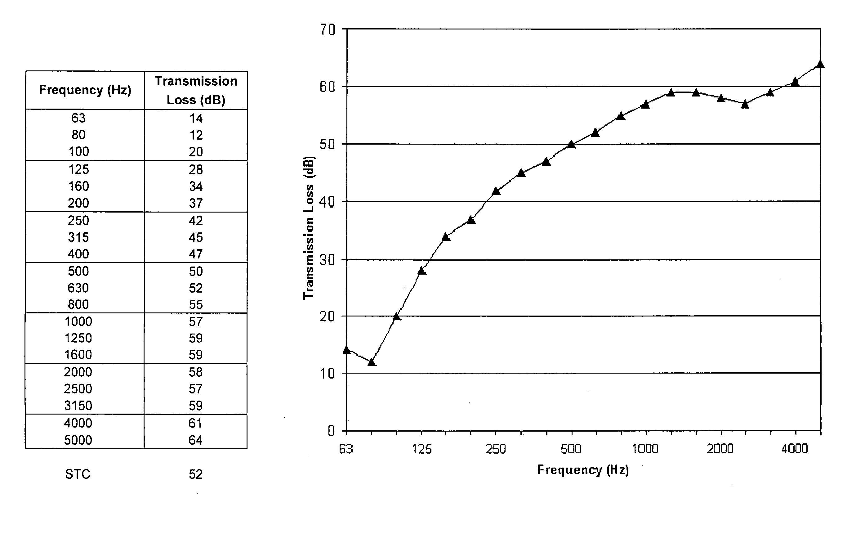
[0021] The present invention is a composite laminate wallboard panel for use in place of standard gypsum panels. The invention is similar in weight to a standard gypsum panel and can be handled and installed in a manner similar to such panels. However, the invention also provides superior noise attenuation, thermal insulation, fire resistance, shear strength, mold resistance, and moisture resistance.
[0022] Noise attenuation in the current invention is enhanced over panels constructed from the prior art, since laminated layers of the current invention have rough, non-uniform surfaces and / or section properties. Surface non-uniformity may be accomplished by embossing, debossing, dimpling, scoring, kerfing, grooving, boring, perforating, scalloping, corrugating, routing, and / or performing other actions that produce surface non-uniformities, such as bonding or attaching in some manner patches of the same or different materials to the surface of the layer. The sizes, shapes, and spatial distribution of these surface features are generally non-uniform, and different types of features can be combined to yield the desired effect. Non-uniformity of the section properties of a layer may be accomplished by embedding one or more different materials and / or voids non-uniformly within the layer, or by constructing the layer as a patchwork of different materials. The sizes, shapes, material types, and spatial distribution of these embedded materials or voids are generally non-uniform, and different embedded features can be combined to yield the desired effect. Further, surface and section non-uniformity may be employed together in the same layer to yield the desired effect.

Problems solved by technology

Further, surface and section non-uniformity may be employed together in the same layer to yield the desired effect.

Method used


Image

  • Noise-attenuating laminate composite wallboard panel and methods for manufacturing same
  • Noise-attenuating laminate composite wallboard panel and methods for manufacturing same
  • Noise-attenuating laminate composite wallboard panel and methods for manufacturing same

Examples


Embodiment Construction

[0034] The following description is intended to be exemplary only and not to in any way limit the scope or objective of the invention. The preferred embodiments referred to below describe a laminate composite wallboard system. This invention, however, is not limited to wallboards, but can be used in any application where a noise-attenuating building material is desired.

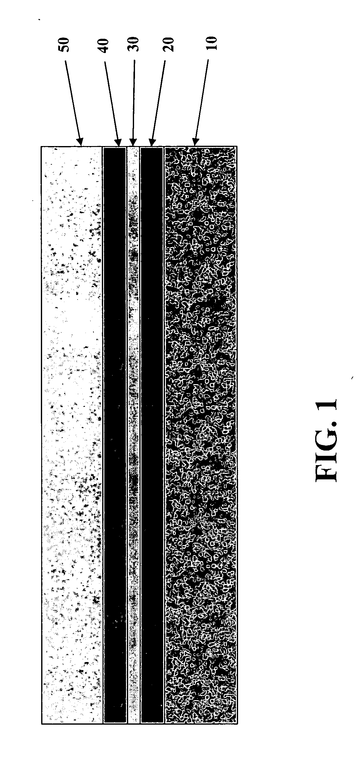
[0035]FIG. 1 shows a cross-section of a preferred embodiment of a wallboard panel constructed with the present invention, which wallboard panel is a five-layer laminate consisting of a standard gypsum panel 10 whose non-facing side is adjacent to a layer of viscoelastic adhesive 20. On the side of the viscoelastic adhesive 20 away from the gypsum panel 10 is a layer of absorbent paper 30. Then, on the side of the absorbent paper 30 away from the viscoelastic adhesive 20 is another layer of viscoelastic adhesive 40. Then, on the side of viscoelastic adhesive 40 away from the absorbent paper 30 is an MgO panel 50.

[003...


PUM


Abstract

A laminate composite wallboard panel is disclosed having multiple layers whose cross sections may contain internal and external non-uniformities and whose surfaces may be rough and non-uniform. The wallboard panel is similar in size and weight to a standard gypsum panel and can be handled and installed in a manner similar to such a panel. The wallboard panel also provides high degrees of noise attenuation, thermal insulation, fire resistance, shear strength, mold resistance and moisture resistance.

Description

FEDERALLY SPONSORED RESEARCH AND DEVELOPMENT STATEMENT [0001] This invention was not developed in conjunction with any Federally sponsored contract. BACKGROUND OF THE INVENTION [0002] 1. Field of the Invention [0003] This invention relates generally to building materials and, more particularly, to a laminate composite panel for use in residential and commercial buildings. [0004] 2. Prior Art [0005] Gypsum-based panels were first used to construct the interior walls of buildings nearly 100 years ago. Since then, the standard design of such panels has consisted of a gypsum core sandwiched between two layers of paper. Commercially available panels generally have gypsum cores ranging in thickness from ¼″ to ¾″, while the panels' large surfaces typically have widths of 48″ or 54″ and lengths ranging from 8′ to 12′ in one-foot increments. Within the construction trade, gypsum-based panels are interchangeably referred to as “drywall,”“wallboard,”“gypsum wallboard,” and “gypsum panels,” whi...

Claims


Application Information

Patent Timeline
Patent Type & Authority Applications(United States)
IPC IPC(8): E04B1/82E04B1/92
CPCB32B13/08E04B2001/8461E04B1/86B32B29/06
Inventor AVERILL, RONALD C.
Owner AVERILL RONALD C
Learn More