Ultrasonic sensor for use in automotive vehicle

Inactive Publication Date: 2008-04-17
DENSO CORP
View PDF7 Cites 4 Cited by
  • Summary
  • Abstract
  • Description
  • Claims
  • Application Information

AI Technical Summary

Benefits of technology

[0010]Neighboring receiving regions are separated by a intercepting slit for suppressing crosstalk between the neighboring receiving regions. The intercepting slit extends in a direction substantially perpendicular to the second surface of the receiving member and has an opening open to the second surface and a closed end in the receiving member. The slit is made to satisfy a formula: 0.35≦L / T≦0.6, where L is a depth of the intercepting slit and T is a thickness of the receiving member. By making the intercepting slit in this shape, the crosstalk between neighboring regions, which results in detection noises, is effectively suppressed or eliminated.
[0012]By forming the intercepting slit to satisfy a relation L / T=0.45, the crosstalk between neighboring receiving regions is completely intercepted, and thereby the ultrasonic waves received by a receiving region corresponding to a vibrating portion are exclusively propagated to that vibrating portion, completely eliminating noises due to the crosstalk. The detection sensitivity of the ultrasonic sensor is maximized by making the intercepting slit to satisfy the relation L / T=0.45.
[0013]When the depth L of the intercepting slit is made smaller than 0.45T and larger than 0.35T, the crosstalk is sufficiently suppressed while maintaining a mechanical strength of the receiving member. When the depth L of the intercepting slit is made larger than 0.45T and smaller than 0.6T, the crosstalk is sufficiently suppressed and the noises due to the crosstalk are easily processed because the noises are in inverse phase relative to the main signals.

Problems solved by technology

In this structure, however, there is a problem that a crosstalk of the ultrasonic waves occurs in the receiving member.
However, the proposed structure of the ultrasonic sensor involves such a problem that a space for filling the intercepting material is required between neighboring vibrating plates.
This makes the ultrasonic sensor large in size and adversely affects an ornamental design of the ultrasonic sensor that is mounted on a bumper of a vehicle.

Method used


Image

  • Ultrasonic sensor for use in automotive vehicle
  • Ultrasonic sensor for use in automotive vehicle
  • Ultrasonic sensor for use in automotive vehicle

Examples


Embodiment Construction

[0024]A preferred embodiment of the present invention will be described with reference to accompanying drawings. The embodiment shown herein is an ultrasonic sensor to be mounted on an automotive vehicle for detecting an obstacle or obstacles located around the vehicle.

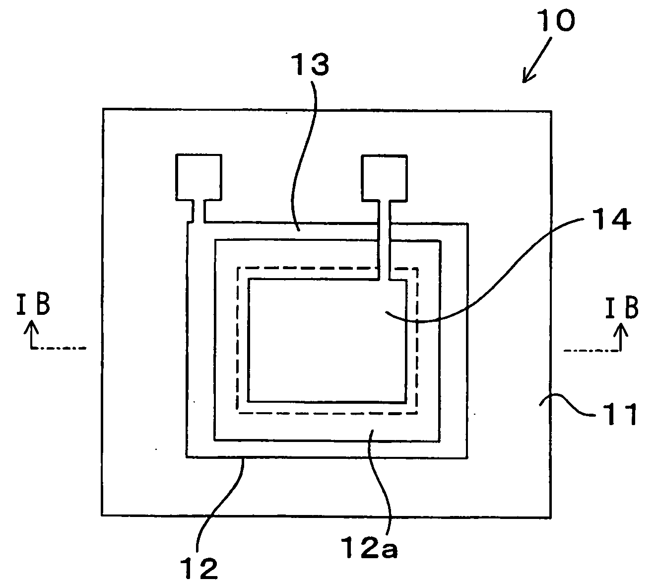
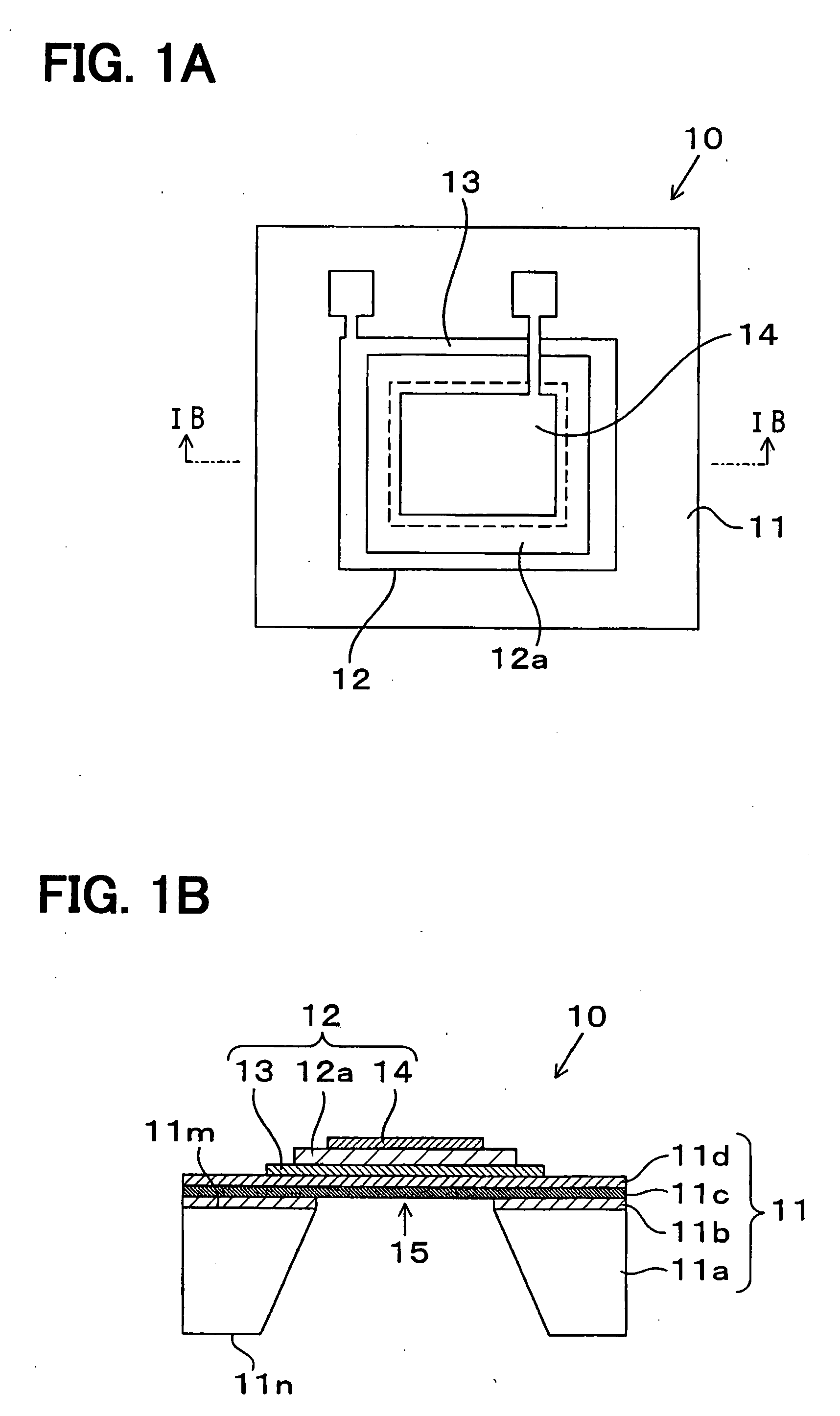
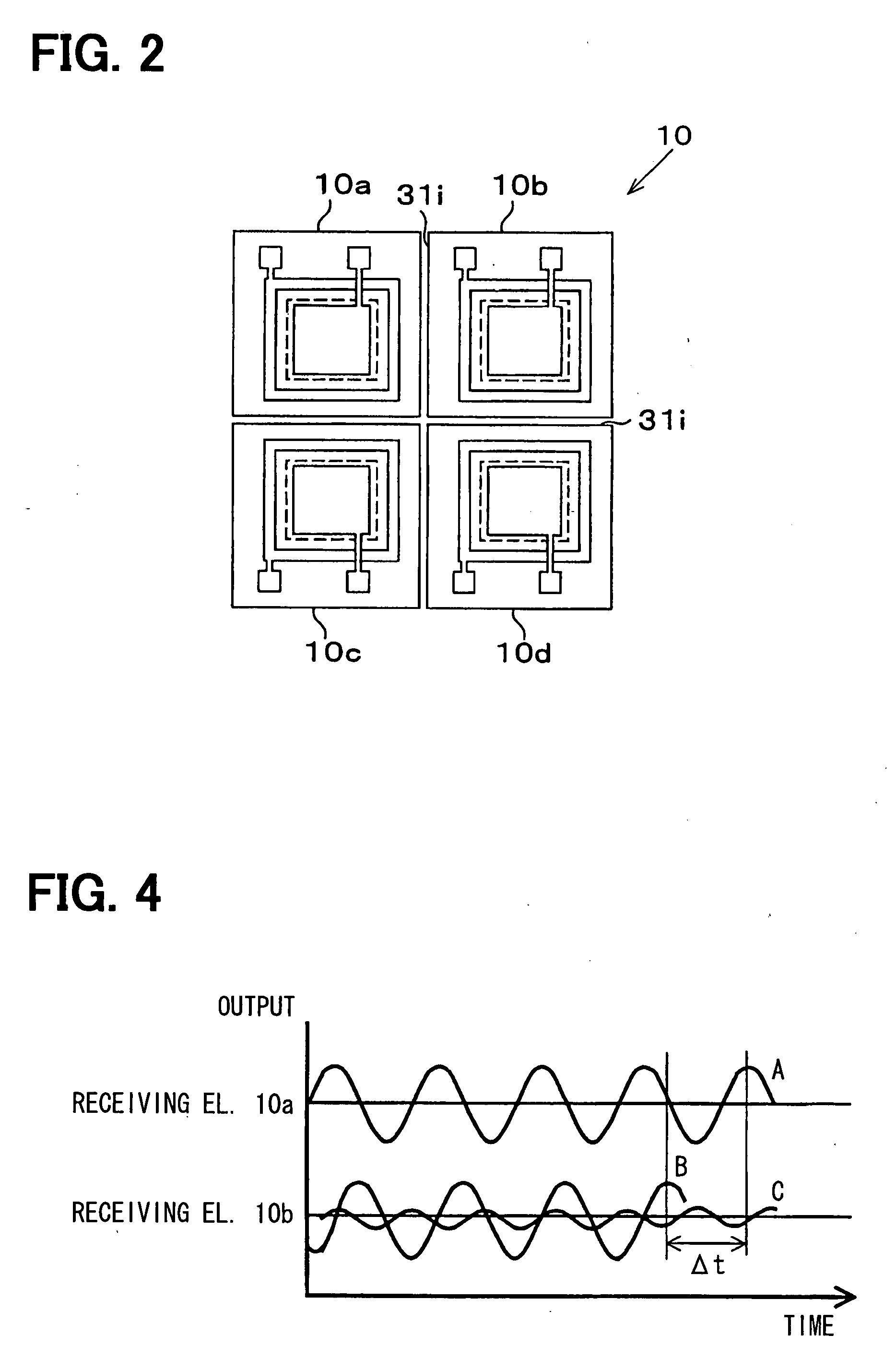
[0025]First, a receiving element 10 that includes plural individual receiving elements will be described. In this particular embodiment, four individual receiving elements 10a-10d are formed on the receiving element 10, as shown in FIG. 2. FIG. 1A shows an individual receiving element (the individual receiving elements 10a-10d are all the same, and each of them is generally referred to as a receiving element 10), and FIG. 1B shows a cross-sectional view of the receiving element 10.

[0026]As shown in FIG. 1B, the receiving element 10 is formed on a semiconductor substrate 11 such as a silicon-on-insulator (SOI) substrate. On the upper surface 11m of the semiconductor substrate, a first insulation film 11b, a silicon act...


PUM


Abstract

An ultrasonic sensor for detecting a position and / or a shape of an object located around an automotive vehicle is mounted on a structure of the vehicle such as a bumper. The ultrasonic sensor includes a receiving member for receiving ultrasonic waves reflected on the object to be detected and receiving element having plural vibrating portions. The receiving member is sectioned by intercepting slits into plural receiving regions each corresponding to each vibrating portion. The intercepting slit eliminates or suppresses crosstalk between neighboring receiving regions, and thereby reducing detection noises due to the crosstalk and improving detection sensitivity of the ultrasonic sensor. The shape of the intercepting slit is made to satisfy the formula: 0.35≦L / T≦0.60, where L is a depth of the slit and T is a thickness of the receiving member. In this manner, the crosstalk resulting in detection noises is sufficiently suppressed.

Description

CROSS-REFERENCE TO RELATED APPLICATION[0001]This application is based upon and claims benefit of priority of Japanese Patent Application No. 2006-280021 filed on Oct. 13, 2006, the content of which is incorporated herein by reference.BACKGROUND OF THE INVENTION[0002]1. Field of the Invention[0003]The present invention relates to an ultrasonic sensor for use in an automotive vehicle, the ultrasonic sensor receiving ultrasonic waves reflected on an object to be detected.[0004]2. Description of Related Art[0005]Recently, an ultrasonic sensor has been mounted on an automotive vehicle to detect an obstacle located around the vehicle. Ultrasonic waves are transmitted from the vehicle, and the ultrasonic waves reflected on the obstacle are received by the ultrasonic sensor mounted on the vehicle. A distance of the obstacle from the vehicle and / or its two-dimensional or three-dimensional shape are detected based on the transmitted and received ultrasonic waves.[0006]In this type of sensor, ...

Claims


Application Information

Patent Timeline
IPC IPC(8): G01H5/00
CPCG01H11/06G01S7/521G01H11/08
Inventor WATANABE, KAZUAKISUGIURA, MAKIKOOKUDA, YASUYUKI
Owner DENSO CORP
Why Eureka
Try Eureka