Internal combustion engine
a combustion engine and internal combustion technology, applied in combustion engines, machines/engines, output power, etc., can solve the problems of undesirable engine knock, deterioration of fuel economy at low engine load, and increase in the temperature of the intake air drawn into the combustion chamber, so as to reduce the cooling loss and improve the thermal efficiency
- Summary
- Abstract
- Description
- Claims
- Application Information
AI Technical Summary
Benefits of technology
Problems solved by technology
Method used
Image
Examples
first embodiment
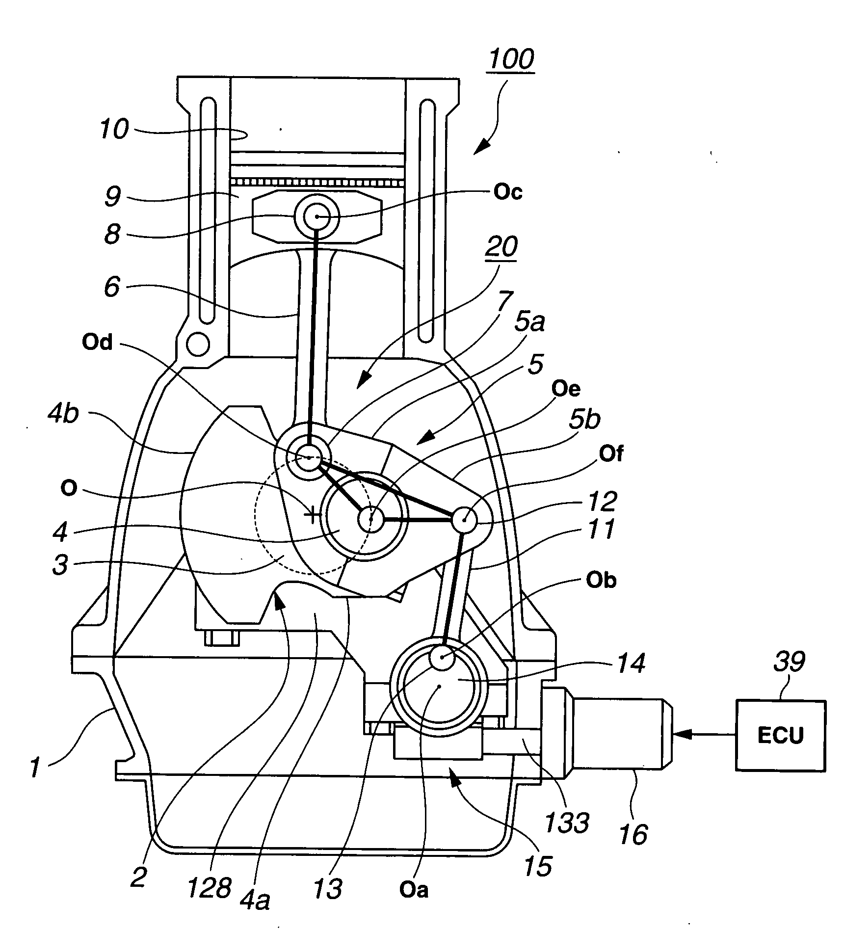
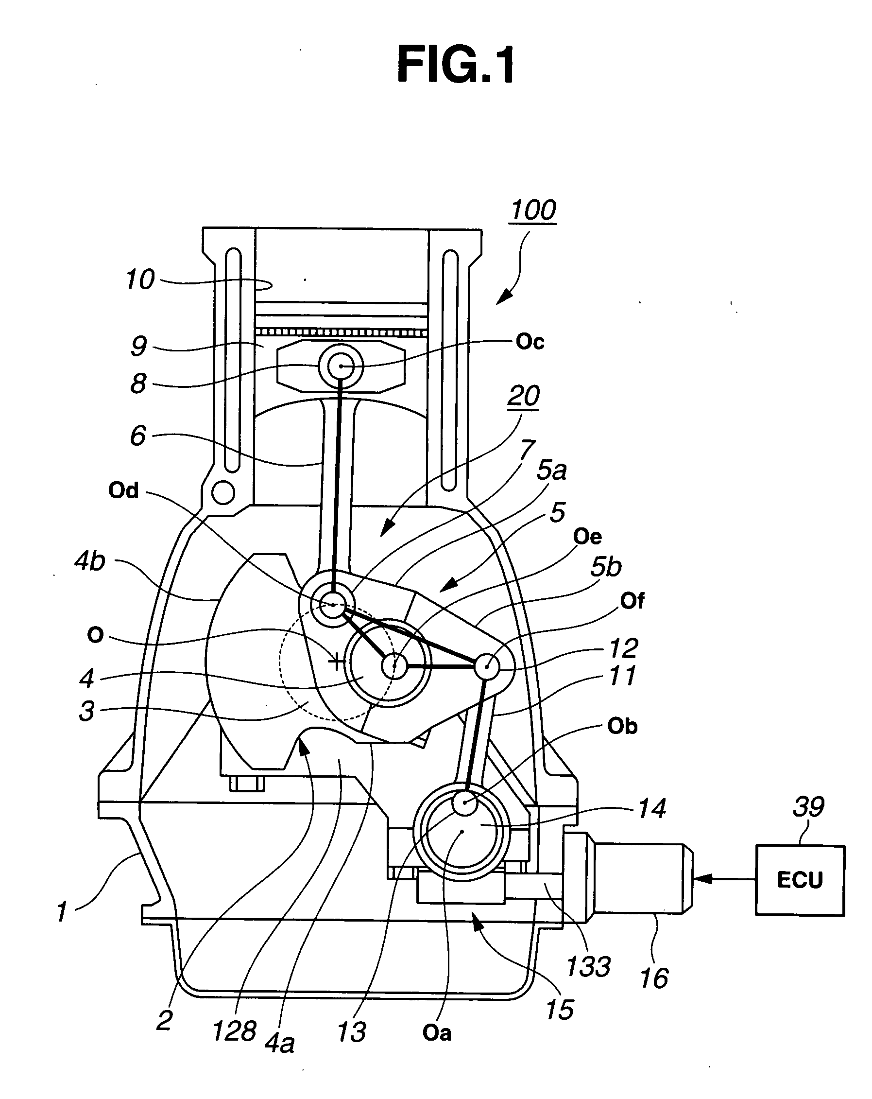
[0065]Referring now to FIG. 3B, there is shown the thermal-insulation piston and thermal-insulation cylinder liner structure, which is applicable to piston 9 and cylinder 10 of multi-link reciprocating internal combustion engine 100 of the In FIG. 3B, piston rings denoted by reference signs 51-52 are compression rings installed for sealing the compression into the combustion chamber 62, whereas a piston ring denoted by reference sign 53 is an oil-control ring installed to scrape excessive oil off the cylinder wall. As seen in FIG. 3B, a coating layer (or a thermal-insulation area or a thermal-insulation portion) 55 of a predetermined thickness, formed of a thermal insulation material (a non-metallic material) such as a ceramic material, is formed on the piston crown of a thermal-insulation piston 9B by way of thermal spraying or the like. Additionally, as can be seen from the cross section of FIG. 3B, a cylinder liner 56 is inserted in the engine cylinder block as a separate cylind...
third embodiment
[0129]Details of the 1st and 2nd Ne-Tq-εm characteristic maps of FIGS. 12A-12B used in the engine of the third embodiment are hereunder described.
[0130]As can be seen from the 1st and 2nd maps respectively shown in FIGS. 12A-12B, the basic tendency of target compression ratio εm varying with respect to engine load (engine torque Tq) and engine speed Ne is similar to that of Ne-Tq-εm characteristic map shown in FIG. 6 used in the engines of the first and second embodiments. That is, as can be appreciated from the characteristic curves of the 1st and 2nd Ne-Tq-εm characteristic maps shown in FIGS. 12A-12B, under a low engine load condition, target compression ratio εm is set to a high value. Conversely, under a high engine load condition, target compression ratio εm is set to a relatively low value, in comparison with the low engine load condition. In a high engine speed range, target compression ratio εm is set to a high value. Conversely in a low engine speed range, target compressi...
fourth embodiment
[0198] in which variable compression ratio reciprocating piston engine 100 is combined with at least variable valve operating system 200, it is possible to increase geometrical compression ratio ε depending on intake valve closure timing IVC by means of variable compression ratio mechanism 20 of variable compression ratio engine 100. However, when geometrical compression ratio ε is controlled to a high value, the clearance space shape of the combustion chamber with the piston at TDC on the compression stroke becomes excessively flattened, thus increasing a cooling loss at TDC on the compression stroke. Therefore, on the one hand, increasing the engine compression ratio (geometrical compression ratio ε) improves an undesirable compression temperature fall at TDC on the compression stroke. On the other hand, increasing the engine compression ratio ε leads to an increase in cooling loss. This does not lead to the improvement of the thermal efficiency.
[0199]In order to avoid the cooling...
PUM
 Abstract
Description
Claims
Application Information
 - R&D
- Intellectual Property
- Life Sciences
- Materials
- Tech Scout
- Unparalleled Data Quality
- Higher Quality Content
- 60% Fewer Hallucinations
Browse by: Latest US Patents, China's latest patents, Technical Efficacy Thesaurus, Application Domain, Technology Topic, Popular Technical Reports.
© 2025 PatSnap. All rights reserved.Legal|Privacy policy|Modern Slavery Act Transparency Statement|Sitemap|About US| Contact US: help@patsnap.com


