
Method and Plant for Transport of Rich Gas

a rich gas and pipeline technology, applied in mechanical equipment, gas/liquid distribution and storage, fuel supply equipment, etc., can solve the problems of unwelcome temperature and pressure drop along the pipeline, and inability to meet the needs of customers, so as to reduce the cricondentherm and cricondentherm, and prevent the effect of liquid condensation in the pipelin

Inactive Publication Date: 2008-04-17
SARGAS
View PDF14 Cites 5 Cited by
  • Summary
  • Abstract
  • Description
  • Claims
  • Application Information

AI Technical Summary

Benefits of technology

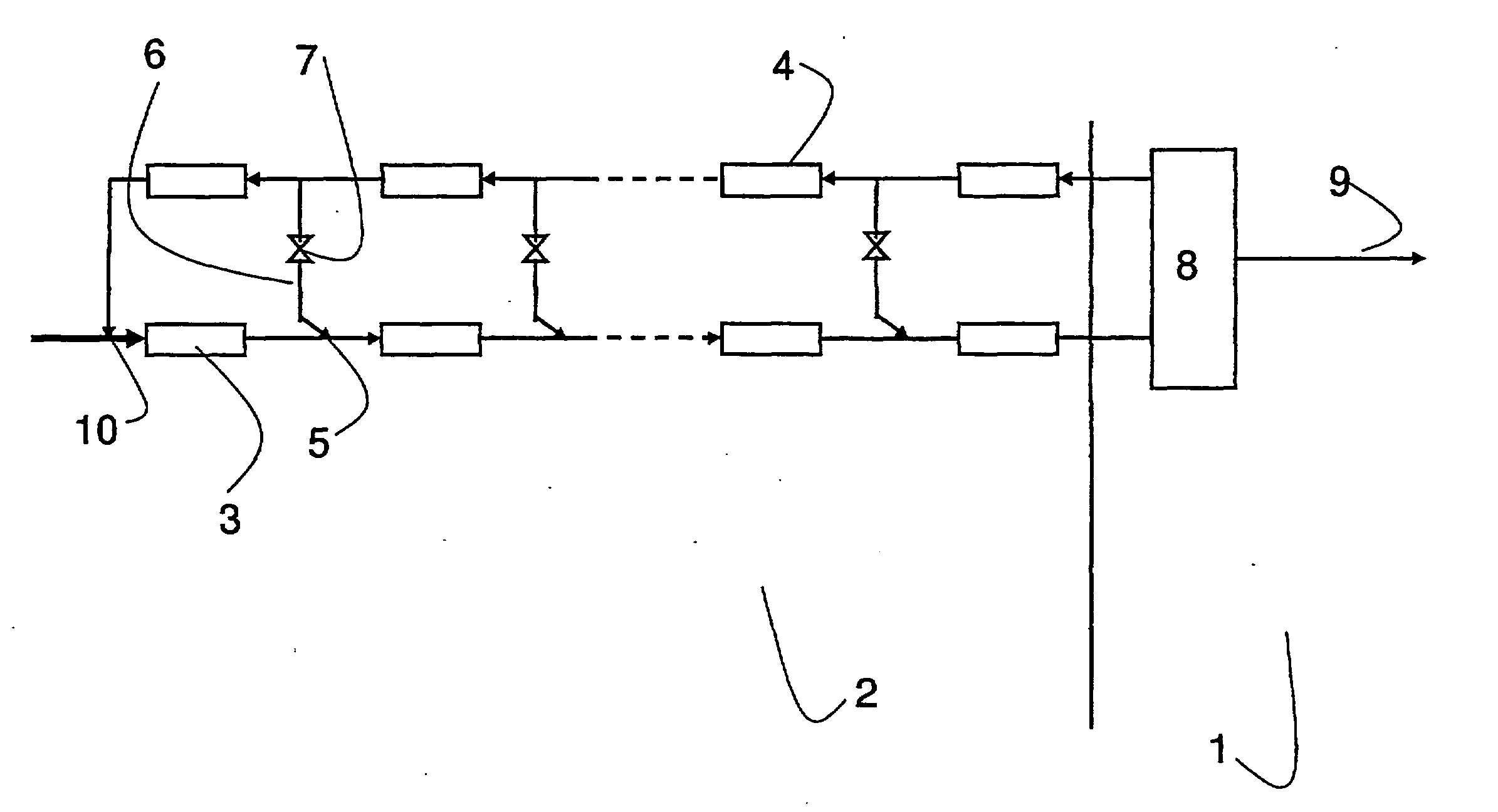
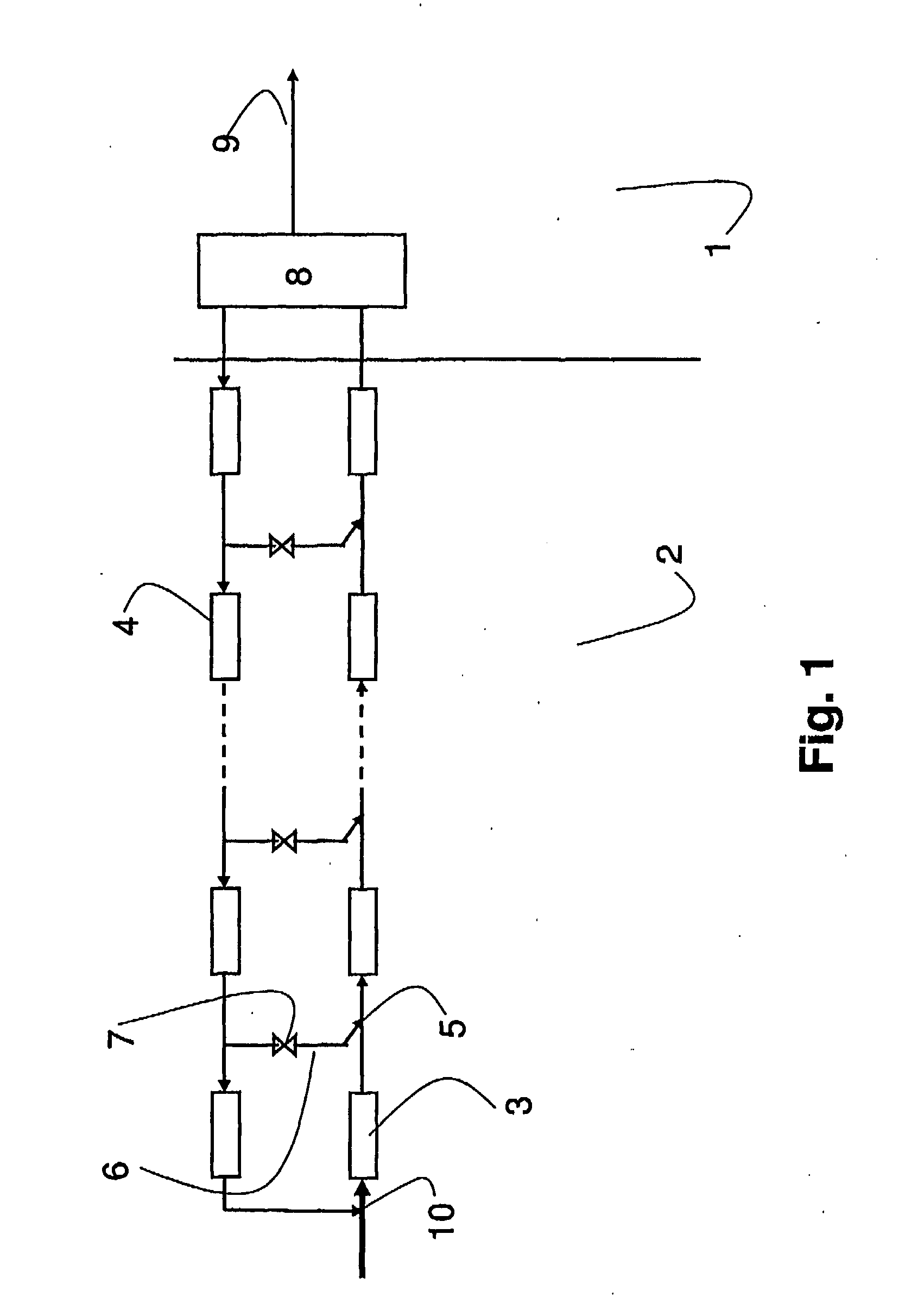
[0008] According to a first aspect, the present invention relates to a method for transport of natural gas through a pipeline from a gas field to a terminal, where there is a risk of condensation of heavy hydrocarbon components in the pipeline during the transport, wherein dry gas is added to the natural gas to reduce the cricondentherm and the cricondentherm of the gas and thus prevent condensation in the pipeline.
[0009] Preferably the dry gas additionally is used to increase the pressure of the gas in the pipeline. The increased pressure increases the difference between the pressure of the gas and the cricondenbar of the gas, resulting in reduced risk for condensation of hydrocarbons.
[0010] Addition of the dry gas serves to increase the velocity of the gas in the pipeline, in particular when the gas field has a reduced production rate such as in late field life or during periods with reduced gas demand. The major benefit of keeping a high velocity in the pipeline is that the gas will then sweep any liquids, such as water or water / glycol mixtures, out of the pipeline. Liquids therefore will not accumulate in the pipeline, but are removed efficiently on a continual basis regardless of the gas production rate. This reduces the need for pipeline scrapers.
[0011] According to an embodiment, the pressure of the gas is increased by injecting the dry gas at high pressure, parallel with the current in the pipeline.
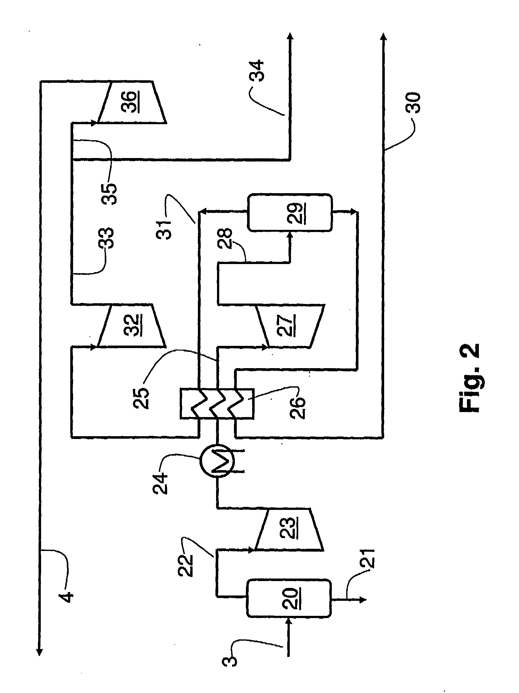
[0012] According to an alternative embodiment, the pressure of the gas is increased by means of compressors propelled by expansion of the dry gas prior to injection into the pipeline.
[0015] According to a preferred embodiment, the gas in the pipeline is separated at the terminal in wet gas fraction and a dry gas fraction, where at least a portion of the dry gas is returned to the gas field to be added to the natural gas to prevent condensation of heavy components in the pipeline.

Problems solved by technology

The long distance from the gas field combined with the rough climate and great ocean depths makes the traditional production platforms impractical and too expensive, and makes it more preferable to use sub-sea production facilities and sub-sea pipelines for transporting the gas ashore before treatment.
Even if the temperature and pressure at the production end of a pipeline are sufficiently high to keep all the components in the natural gas in gas phase, both the temperature and pressure fall along the pipeline due to heat loss and friction.
The condensation of liquid in the pipeline is unwanted as it results in multiphase flow in the pipeline.
Multiphase flow is a very complicated phenomenon.
Multiphase flow results in increased friction loss, accumulation of large amounts of liquid in the pipeline, potentially slug flow and increased risk for corrosion of the pipeline.
The increased risk for corrosion makes it necessary to use high grade steel in the pipeline, thus increasing the cost.
The separation does, however, require process facilities not available in remote sub-sea production facilities.
Booster stations increase the cost of the pipeline, and are additionally expected to require frequent maintenance, which may result in expensive production stops and problems during restart of the station.
This is a fairly complex process which consumes large amounts of energy.
Typically, the energy must be produced locally, adding complexity and cost.

Method used


Image

  • Method and Plant for Transport of Rich Gas
  • Method and Plant for Transport of Rich Gas
  • Method and Plant for Transport of Rich Gas

Examples


example

[0047] A natural gas having a mean molar weight of 22.2 kg / kgmol, a cricondentherm of 31° C. and a cricondenbar of 105.4 bara, is mixed with a dry gas having a mean molar weight of 16.8 kg 7 kgmol, a cricondentherm of −65.1° C. and a cricondenbar of 55.3 bara. The table below gives the cricondenbar and cricondentherm for the resulting mixture.

Natural gas to dry gas ratioCricondenthermCricondenbar1:1.8−1.7° C.88.9 bara1:2.5−7.5° C.86.8 bara

[0048] For both the ratios exemplified in the table, the cricondentherm is reduced from 31° C. to below 0° C., so that condensation of hydrocarbon liquid and the resulting multiphase current, is substantially avoided. The cricondenbar is reduced from 105.4 bara to below 90 bara, giving additional protection against condensation. It is possible to increase the amount of dry gas in the total gas mixture to give even better protection against condensation. An increased share of dry gas in the total gas, will however, reduce the capacity of the main ...


PUM


Abstract

A method for transport of natural gas through a pipeline from a gas field to a terminal, where there is a risk of condensation of heavy hydrocarbon components in the pipeline during the transport, wherein dry gas is added to the natural gas to reduce the cricondentherm and the cricondentherm of the gas and thus prevent condensation in the pipeline, is described. A plant for carrying out the method is also described.

Description

FIELD OF INVENTION [0001] The present invention relates to offshore technology, more specifically to transport of gas in pipelines ashore from a gas field or transport between gas fields. TECHNICAL BACKGROUND [0002] Offshore gas fields may be situated far away from the shore. Additionally, some of the large gas fields discovered the latest years are situated in remote ocean areas having a rough climate, like the Norwegian Sea and the Barents Sea. The long distance from the gas field combined with the rough climate and great ocean depths makes the traditional production platforms impractical and too expensive, and makes it more preferable to use sub-sea production facilities and sub-sea pipelines for transporting the gas ashore before treatment. [0003] Untreated natural gas comprises a mixture of light and heavy components. The heavy components have a tendency to condense as a liquid as the temperature and pressure falls. Even if the temperature and pressure at the production end of ...

Claims


Application Information

Patent Timeline
Patent Type & Authority Applications(United States)
IPC IPC(8): F17D1/00F17C
CPCF17D1/005Y10T137/0391Y10T137/7025F17D1/02
Inventor CHRISTENSEN, TORFLEISCHER, HENRIKBORSETH, KNUT
Owner SARGAS
Learn More