Fuel cell system and method of operating the same

a fuel cell and system technology, applied in the field of fuel cell systems, can solve the problems of only being able to apply load to the fuel cell, long preheating time, and slow increase in temperature, and achieve the effect of increasing the temperature of the unit cell

Inactive Publication Date: 2008-04-17
SAMSUNG SDI CO LTD
View PDF2 Cites 25 Cited by
  • Summary
  • Abstract
  • Description
  • Claims
  • Application Information

AI Technical Summary

Benefits of technology

[0010]Aspects of the present invention provide a fuel cell system that can rapidly increase the temperature of unit cells when necessary, and a method of operating the fuel cell.

Problems solved by technology

However, conventionally, a unit cell 10 does not generate a useable high voltage.
However, when a fuel cell system is configured and operated as described above, the preheating time is long. FIG. 2 is a graph showing the measurement results of temperature vs. voltage of each unit cell when a normal operation begins.
However, as depicted in FIG. 2, the increase in temperature is very slow.
That is, a load can only be applied to the fuel cell almost one hour after start up of the fuel cell.

Method used


Image

  • Fuel cell system and method of operating the same
  • Fuel cell system and method of operating the same
  • Fuel cell system and method of operating the same

Examples


Embodiment Construction

[0025]Reference will now be made in detail to the present embodiments of the present invention, examples of which are illustrated in the accompanying drawings, wherein like reference numerals refer to the like elements throughout. The embodiments are described below in order to explain the present invention by referring to the figures.

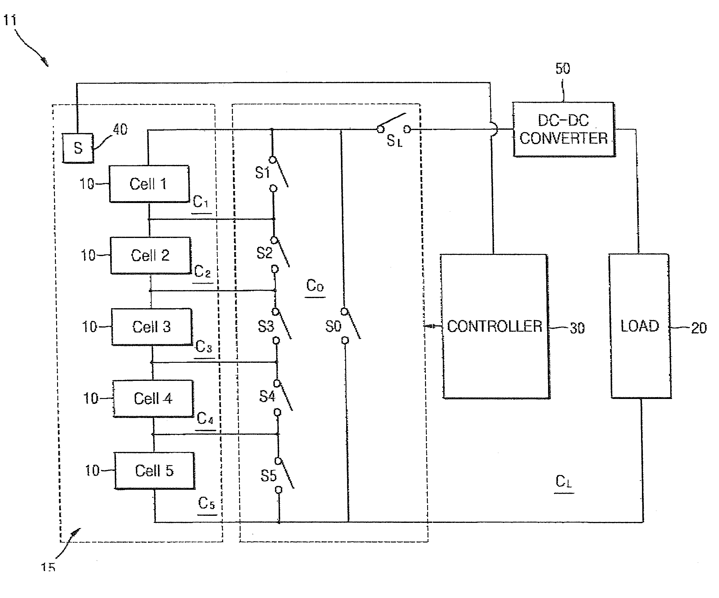
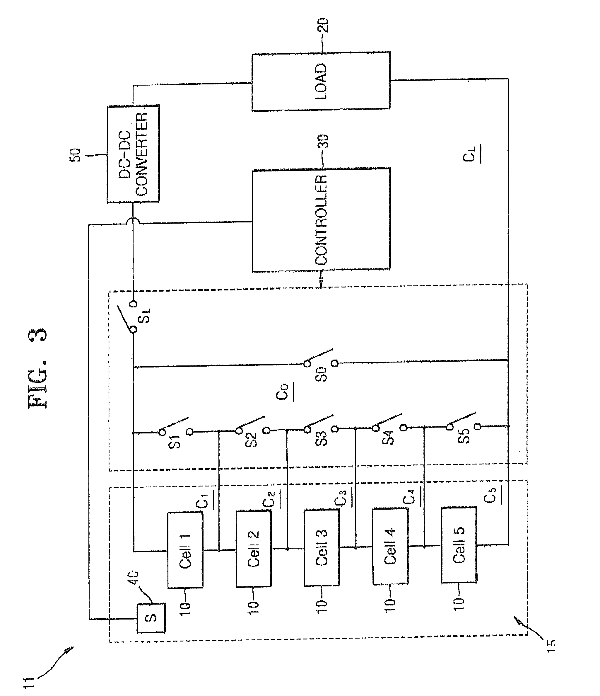
[0026]FIG. 3 is a block diagram showing an overall configuration of a fuel cell system 11 according to an embodiment of the present invention.

[0027]The fuel cell system 11 comprises: a plurality of unit cells 10 disposed in a stack 15; a load 20; a controller 30; a temperature sensor 40; and a DC-DC converter 50. The stack 15 comprises a stack anode and a stack cathode. The unit cells 10 can be connected to one another in series. Each of the unit cells 10 comprises a cell anode and a cell cathode. The load 20 can comprise any electrical device that provides resistance to an electrical current, for example, a motor or any other electrically operated dev...


PUM

PropertyMeasurementUnit
operating temperatureaaaaaaaaaa
operating voltageaaaaaaaaaa
operating temperatureaaaaaaaaaa

Abstract

A fuel cell system to rapidly increase the temperature of unit cells. The fuel cell system includes; a plurality of current generating unit cells; a load circuit to supply the current to a load; a short circuit to connect the cells to an electrically closed loop without passing through the load; a thermo sensor to measure the temperature of the cells, and a controller that controls the delivery of the current to the load circuit and the short circuit, according to the temperature measured by the thermo sensor. The fuel cell system can rapidly increase the temperature of the unit cells when the temperature of the unit cells is below an operating temperature, thereby reducing the time required for the fuel cell to generate a stable output voltage.

Description

CROSS-REFERENCE TO RELATED APPLICATIONS[0001]This application claims the benefit of Korean Patent Application No. 2006-101046, filed on Oct. 17, 2006, in the Korean Intellectual Property Office, the disclosure of which is incorporated herein by reference.BACKGROUND OF THE INVENTION[0002]1. Field of the Invention[0003]Aspects of the present invention relate to a fuel cell system and a method of operating the same.[0004]2. Description of the Related Art[0005]A fuel cell is an electric generator that converts the chemical energy of a fuel into electrical energy through a chemical reaction. A fuel cell can continuously generate electricity for as long as fuel is supplied thereto. FIG. 1 is a schematic drawing illustrating the energy transformation structure of a fuel cell. Referring to FIG. 1, when air that includes oxygen is supplied to a cathode 1, and a fuel containing hydrogen is supplied to an anode 3, electricity is generated by the reverse electrolysis of water through an electro...

Claims


Application Information

Patent Timeline
Patent Type & Authority Applications(United States)
IPC IPC(8): H01M8/04
CPCH01M8/04007H01M8/04037H01M8/04253H01M8/04268Y02E60/50H01M8/04559H01M8/04701H01M8/04902H01M8/0432H01M8/04
Inventor KIM, YOUNG-JAELEE, JAE-YONGKIM, JIN-HOCHO, HYE-JUNGHU, LEIJOUNG, YOUNG-SOO
Owner SAMSUNG SDI CO LTD
Why Eureka
Try Eureka