Bone treatment systems and methods

a bone treatment and vertebral compression technology, applied in the field of vertebral compression fracture treatment systems and methods, can solve the problems of fractures in the spine and hips, affecting mobility and quality of life, and the medical advances aimed at slowing or arresting bone loss from aging have not provided solutions to this problem

Inactive Publication Date: 2008-04-17
DFINE INC
View PDF14 Cites 152 Cited by
  • Summary
  • Abstract
  • Description
  • Claims
  • Application Information

AI Technical Summary

Benefits of technology

[0018] In accordance with one embodiment, a method for treating bone is provided. The method comprises providing an elongated shaft capable of linear and curved shapes about a flex axis, and a shaft-associated cutting element that is adapted to assume a first configuration co-linear the shaft and flex axis and adapted to assume a second configuration that is not co-linear with the shaft and flex axis when the shaft is curved. The method also comprises positioning the shaft in cancellous bone in a curved shape and actuating the cutting element from the first configuration to the second configuration thereby creating a cut plane in the cancellous bone.
[0020] In accordance with another embodiment, a method of treating a vertebra is provided. The method comprises providing a shaft having an arc-configurable working end with a wire-like cutting element that is extendable away from the working end in a plane across the arc-shape, introducing the working end into cancellous bone in a vertebra, causing the working end to extend at least about 90° in an arc configuration in the cancellous bone, and extending a cutting element from the working end across the arc configuration to thereby cut bone.

Problems solved by technology

Medical advances aimed at slowing or arresting bone loss from aging have not provided solutions to this problem.
Osteoporosis affects the entire skeleton but most commonly causes fractures in the spine and hip.
Spinal or vertebral fractures also cause other serious side effects, with patients suffering from loss of height, deformity and persistent pain which can significantly impair mobility and quality of life.
Osteoporosis describes a condition of decreased bone mass that leads to fragile bones which are at an increased risk for fractures.
In an osteoporotic bone, the sponge-like cancellous bone has pores or voids that increase in dimension making the bone very fragile.
In an elderly patient, bone resorption can surpass bone formation thus resulting in deterioration of bone density.
Since the PMMA needs to be forced into the cancellous bone, the techniques require high pressures and fairly low viscosity cement.
Since the cortical bone of the targeted vertebra may have a recent fracture, there is the potential of PMMA leakage.
Leakage of PMMA during vertebroplasty can result in very serious complications including compression of adjacent structures that necessitate emergency decompressive surgery.
The exothermic reaction of PMMA carries potential catastrophic consequences if thermal damage were to extend to the dural sac, cord, and nerve roots.
Vertebroplasty patients often return with new pain caused by a new vertebral body fracture.
Leakage of cement into an adjacent disc space during vertebroplasty increases the risk of a new fracture of adjacent vertebral bodies.
Another life-threatening complication of vertebroplasty is pulmonary embolism.
The vapors from PMMA preparation and injection also are cause for concern.
In both higher pressure cement injection (vertebroplasty) and balloon-tamped cementing procedures (kyphoplasty), the methods do not provide for well controlled augmentation of vertebral body height.
Thus, the reduction of a vertebral compression fracture is not optimized or controlled in high pressure balloons as forces of balloon expansion occur in multiple directions.
Expansion of the balloon under high pressures close to cortical bone can fracture the cortical bone, typically the endplates, which can cause regional damage to the cortical bone with the risk of cortical bone necrosis.
Such cortical bone damage is highly undesirable as the endplate and adjacent structures provide nutrients for the disc.
Kyphoplasty also does not provide a distraction mechanism capable of 100% vertebral height restoration.
Further, the kyphoplasty balloons under very high pressure typically apply forces to vertebral endplates within a central region of the cortical bone that may be weak, rather than distributing forces over the endplate.

Method used


Image

  • Bone treatment systems and methods
  • Bone treatment systems and methods
  • Bone treatment systems and methods

Examples


Embodiment Construction

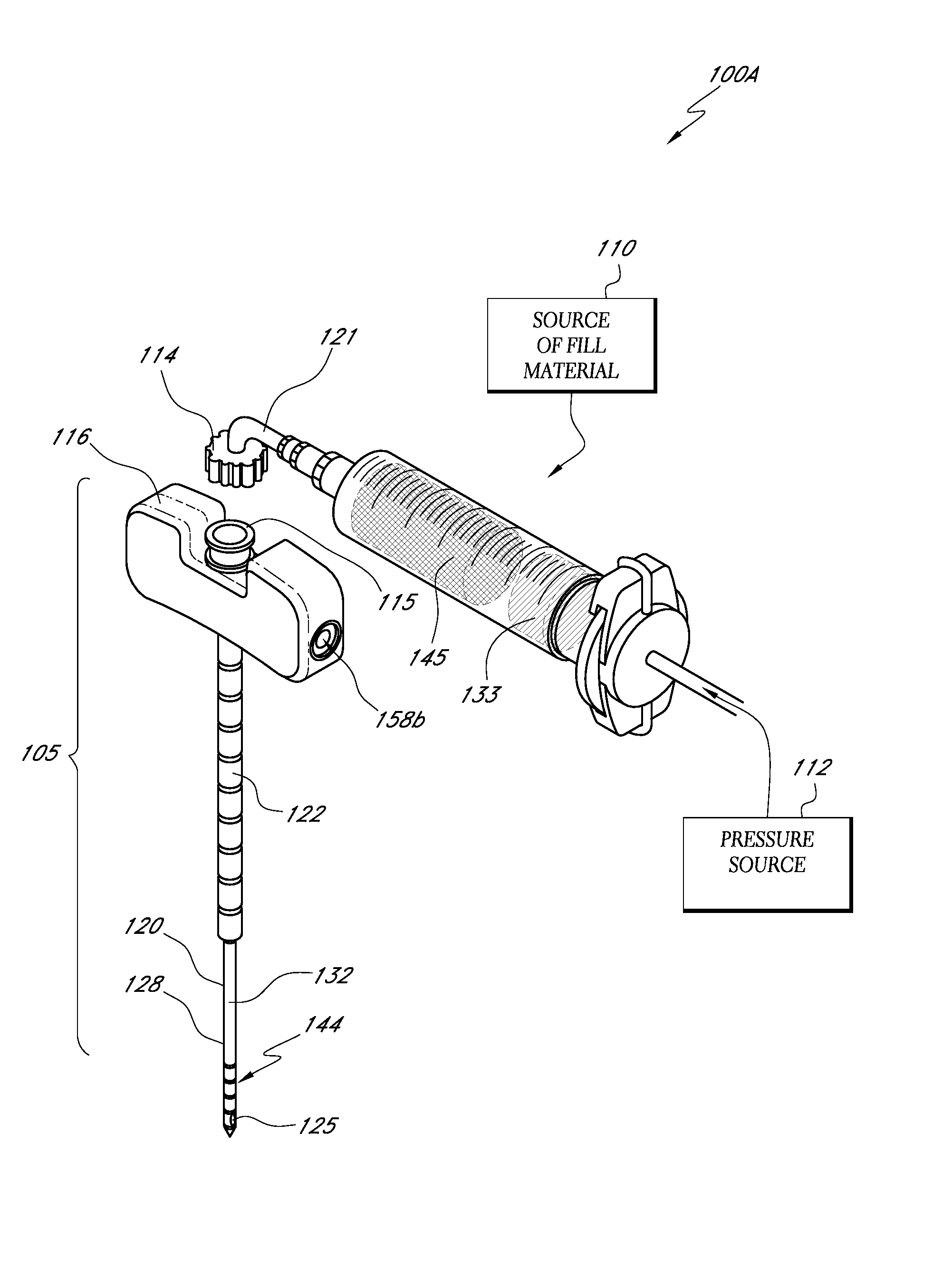
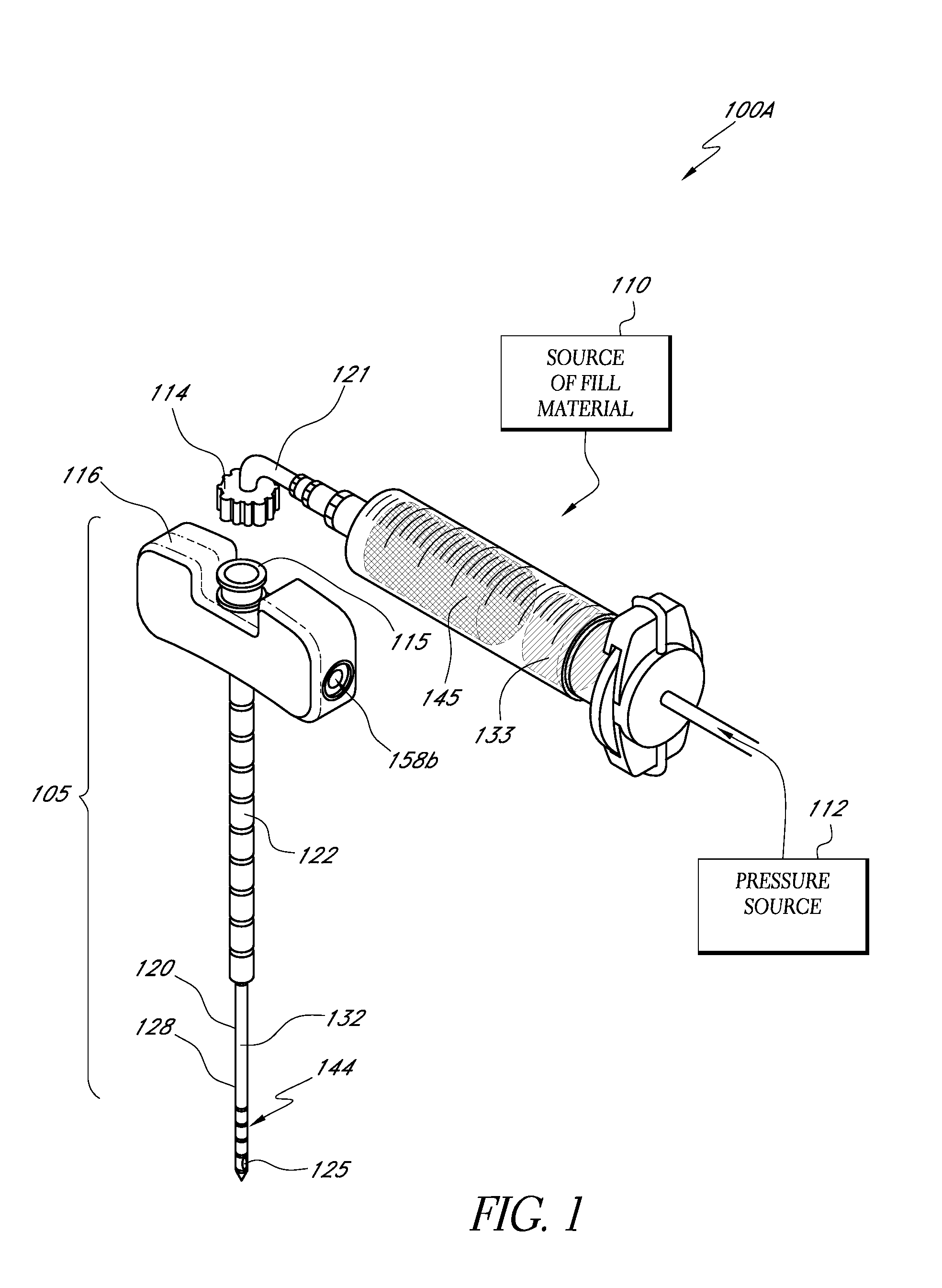
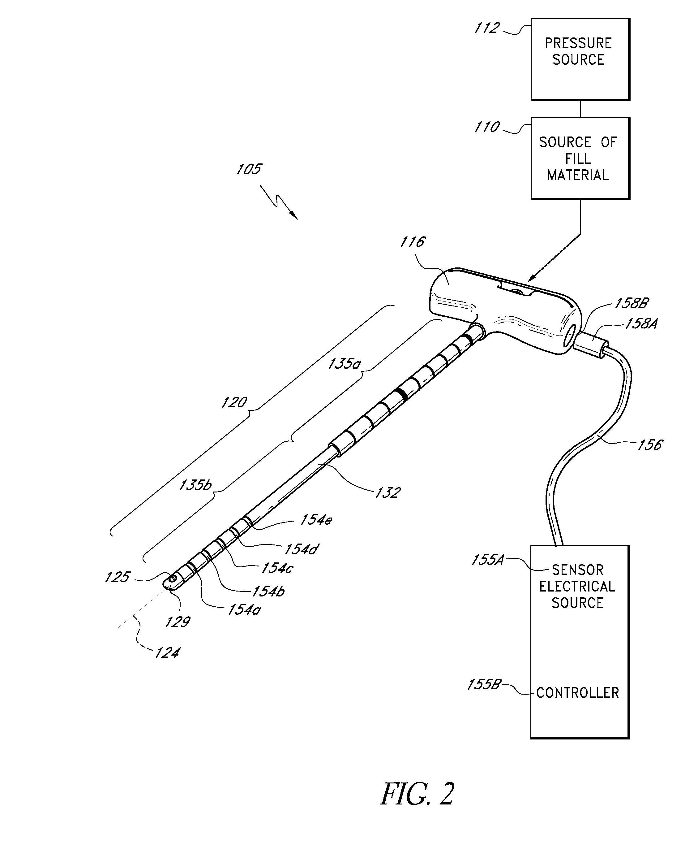
[0040]FIGS. 1-2 show one embodiment of a bone fill introducer or injector system 100A for treatment of the spine in a vertebroplasty procedure. The system 100A can include a bone cement injector 105 coupled to a bone fill material source 110, wherein the injection of the fill material is carried out by a pressure mechanism or source 112 operatively coupled to source 110 of the bone fill material. In one embodiment as in FIG. 1, the pressure source 112 is a hydraulic actuator that is computer controlled. However, in another embodiment, a manually operated syringe loaded with bone fill material, or any other pressurized source of fill material, can be used. The source 110 of fill material includes a coupling or fitting 114 for sealable locking to a cooperating fitting 115 at a proximal end or handle 116 (also see FIG. 4) of the bone cement injector 105 that has an elongated introducer sleeve indicated at 120. In one embodiment, a syringe-type source 110 can be coupled directly to fitt...


PUM


Abstract

Apparatuses, methods, and kits for treating bone (e.g., vertebral compression fractures) includes a shaft with a working end that can be bent into an arc-shaped working end. The shaft can be introduced into a bone (e.g., introduced through a sleeve into cancellous bone) and carries a cutting element that can be actuated across the arc-shaped working end to cut a plane in cancellous bone, which can optionally be filled with a bone fill material (e.g., bone cement).

Description

CROSS-REFERENCE TO RELATED APPLICATIONS [0001] This application claims the benefit of U.S. Provisional Patent Application No. 60 / 851,682 filed Oct. 13, 2006, the entire contents of which are incorporated herein by reference and should be considered a part of this specification. This application is related to the following U.S. patent application Ser. No. 11 / 469,764 filed Sep. 1, 2006 titled Methods for Sensing Retrograde Flows of Bone Fill Material, Ser. No. 11 / 165,652 filed Jun. 24, 2005 titled Bone Treatment Systems and Methods; Ser. No. 60 / 726,152 (Docket No. S-7700-310) filed Oct. 13, 2005 titled Bone Treatment Systems and Methods; and Ser. No. 11 / 209,035 (Docket No. S-7700-280) filed Aug. 22, 2005, titled Bone Treatment Systems and Methods. The entire contents of all of the above applications are hereby incorporated by reference and should be considered a part of this specification.BACKGROUND OF THE INVENTION [0002] 1. Field of the Invention [0003] The present invention relates...

Claims


Application Information

Patent Timeline
Patent Type & Authority Applications(United States)
IPC IPC(8): A61B17/00A61B17/58
CPCA61B17/1671A61B17/320068A61B17/8822A61B2017/00017A61B18/14A61B18/18A61B17/8836A61B2017/320069
Inventor TRUCKAI, CSABALUZZI, ROBERTSHADDUCK, JOHN
Owner DFINE INC
Why Eureka
Try Eureka