
Methods and Apparatus for Time-of-Flight Mass Spectrometer

a mass spectrometer and time-of-flight technology, applied in mass spectrometers, instruments, separation processes, etc., can solve the problems of affecting the measurement accuracy of the mass, the measurement distance or the energy of the time, and the measurement of the error of the mass,

Inactive Publication Date: 2008-04-17
APPL BIOSYSTEMS INC +1
View PDF7 Cites 20 Cited by
  • Summary
  • Abstract
  • Description
  • Claims
  • Application Information

AI Technical Summary

Benefits of technology

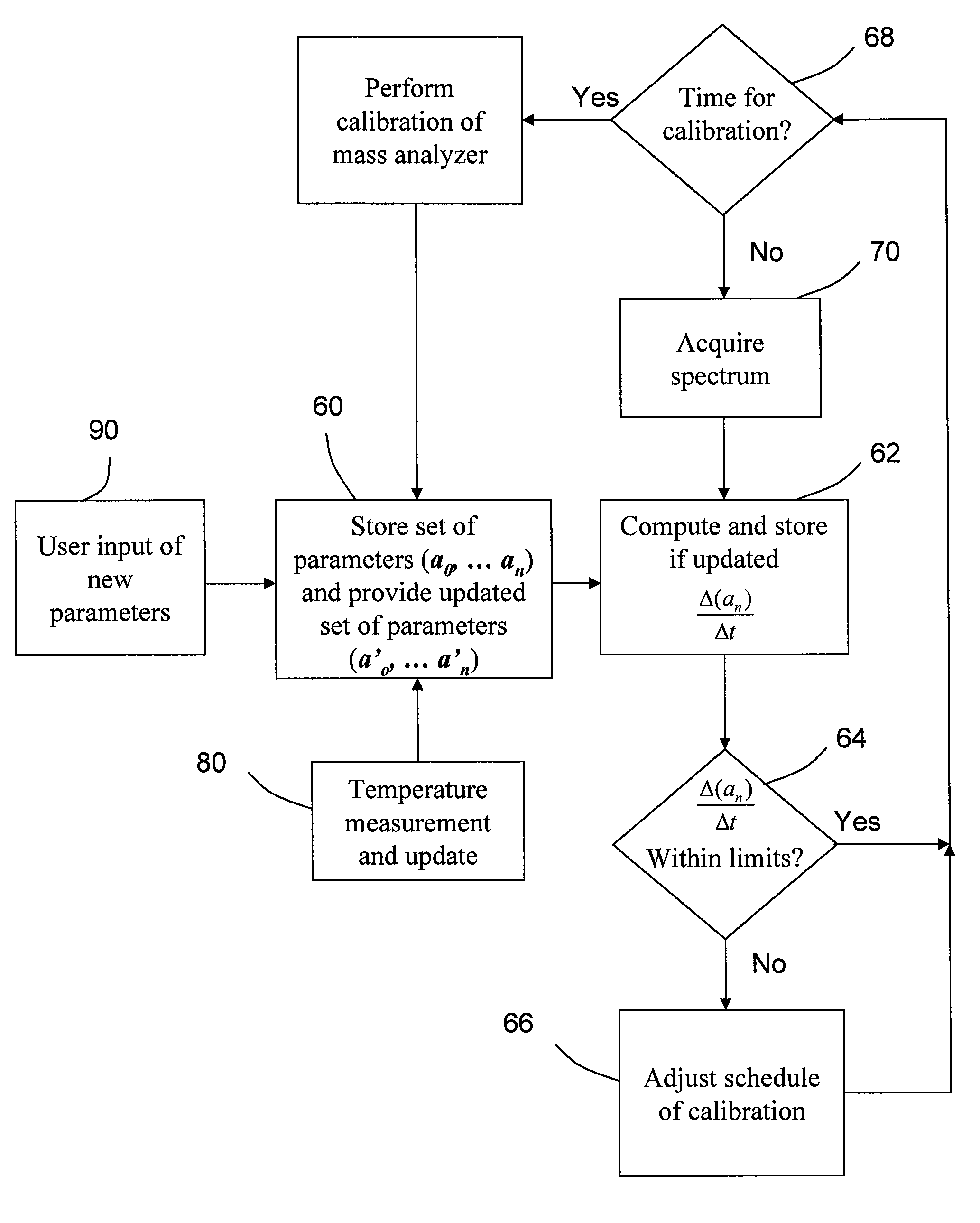
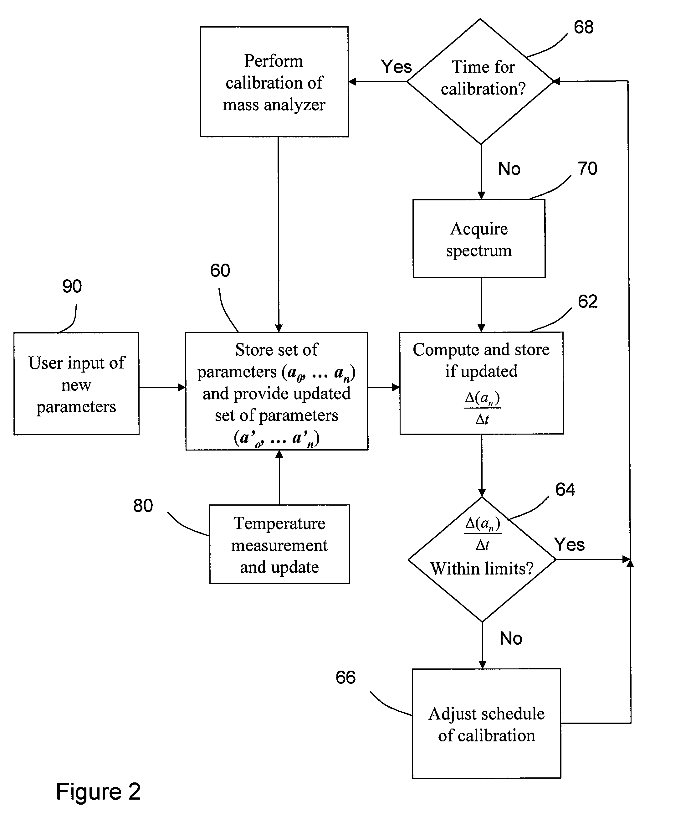
[0006]In view of the foregoing, the present teachings provide a method of determining when to calibrate a time-of-flight mass spectrometer. In various embodiments, the method comprises storing within a controller a set of parameters for the mass spectrometer; providing an updated set of parameters while retaining at least one set of previously stored parameters; computing at least one rate of change of the updated set of parameters with respect to the at least one set of previously stored parameters; and determining when to calibrate the mass spectrometer from the results of computing the rate of change of at least one of the parameters. In various embodiments, a parameter stored can be a set of temperatures derived from obtaining system temperature measurement

Problems solved by technology

Variations of the energy, the distance or the measurement of time, however, may produce errors in measured mass.
It has been proposed to control the temperature of the materials in the TOF MS that undergo expansion and that have an impact on the time-of-flight measurement, but this can be costly and ineffective due to thermal time constants of the affected materials.
Another attempt has been to use the measured temperature to computationally correct the mass spectrum after it is acquired; however, this approach can be burdensome from a data processing standpoint.
Yet running calibrations too frequently when such calibration may be unnecessary results in downtime from sample analysis which has an undesirable effect for high throughput analyses.

Method used


Image

  • Methods and Apparatus for Time-of-Flight Mass Spectrometer
  • Methods and Apparatus for Time-of-Flight Mass Spectrometer
  • Methods and Apparatus for Time-of-Flight Mass Spectrometer

Examples


Embodiment Construction

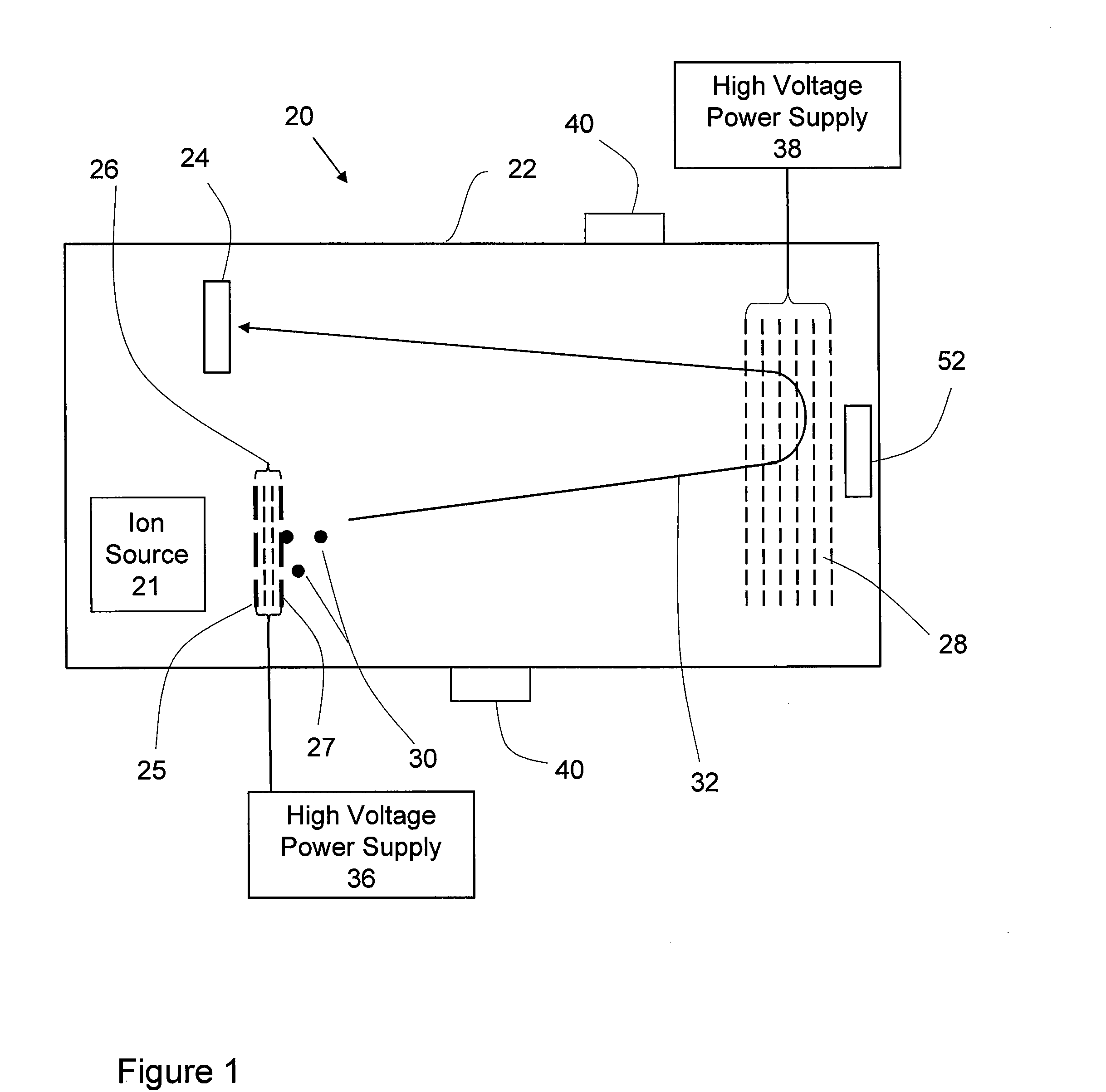
[0013]It should be understood that the phrase “a” or “an” used in conjunction with the present teachings with reference to various elements encompasses “one or more” or “at least one” unless the context clearly indicates otherwise. Reference is first made to FIG. 1, which shows schematically a time-of-flight mass analyzer, generally indicated by reference number 20. In various embodiments, the time-of-flight mass analyzer has an ion source 21, which generally includes a sample support 25 from which ions are desorbed, one or more ion detectors 24, 52 and ion optic components comprising an electrostatic ion accelerator 26 and an electrostatic mirror 28, all located within a vacuum housing 22. The optical and mechanical components through which the ions traverse from source to detector define an ion flight path assembly. In the schematic representation of FIG. 1, the principal components of the ion flight path assembly comprise the vacuum housing 22, the sample support 25, the ion acce...


PUM


Abstract

Disclosed is a method of determining when to calibrate a time-of-flight mass spectrometer. In various embodiments, the method comprises storing within a controller a set of parameters for the mass spectrometer; providing an updated set of parameters while retaining at least one set of previously stored parameters; computing at least one rate of change of the updated set of parameters with respect to the at least one set of previously stored parameters; and determining when to calibrate the mass spectrometer from the results of computing the rate of change of at least one of the parameters. In various embodiments, a parameter stored can be a set of temperatures derived from obtaining system temperature measurements of those components whose changing temperature is an indication of mass drift. In various embodiments, the controller can store a history of calibration factors and temperatures over time, can calculate the time rate of change of the calibration factors and the temperature to estimate the mass drift rate of the instrument and compare the drift rate to a predetermined mass error limit for determining when re-calibration can be scheduled.

Description

INTRODUCTION[0001]The present teachings relate to methods and apparatus for mass spectrometry, and more specifically, the present teachings relate to methods and apparatus for time-of-flight mass spectrometry.[0002]One application for mass spectrometry is directed to the study of biological samples, where sample molecules are converted into ions, in an ionization step, and then detected by a mass analyzer, in mass separation and detection steps. Various types of ionization techniques are presently known, which typically create ions in a region of nominal atmospheric pressure or within vacuum. Mass analyzers can be quadrupole analyzers where RF / DC ion guides are used for transmitting ions within a narrow slice of mass-to-charge ratio (m / z) values, magnetic sector analyzers where a large magnetic field exerts a force perpendicular to the ion motion to deflect ions according to their m / z and time-of-flight (“TOF”) analyzers where measuring the flight time for each ion allows the determ...

Claims


Application Information

Patent Timeline
IPC IPC(8): G01D18/00
CPCH01J49/40H01J49/0009
Inventor GABELER, STEPHEN C.
Owner APPL BIOSYSTEMS INC
Learn More