Scale removal system

a technology of scale removal and system, applied in specific water treatment objectives, electrolysis components, water/sewage treatment by electrochemical methods, etc., can solve the problems of scale components such as silica, magnesium and calcium included in for-treatment water as scales, deterioration of wettability of elements, and remarkable shortening of element life, so as to achieve the effect of avoiding

Inactive Publication Date: 2008-04-24
SANYO ELECTRIC CO LTD
View PDF3 Cites 9 Cited by
  • Summary
  • Abstract
  • Description
  • Claims
  • Application Information

AI Technical Summary

Benefits of technology

[0007] The present invention has been developed to solve such conventional technology problem, and an object is to provide a scale removal system capable of effectively avoiding a disadvantage that a scale is deposited on electrodes and a load.
[0013] In consequence, a disadvantage that the scale is deposited on the load can be avoided. Moreover, the scale is not easily generated at the electrodes, and a disadvantage that the scale is deposited on both of the electrodes and the load can effectively be avoided.
[0014] According to the second invention, the first invention further comprises the channel through which the for-treatment water bypasses the scale collection means. Therefore, even when the scale collection means is clogged, circulation of the for-treatment water can be secured.
[0015] According to the third invention, the first or second invention further comprises the hypochlorous acid resolving means for resolving hypochlorous acid in the for-treatment water. Therefore, the hypochlorous acid resolving means can prevent a disadvantage that a concentration of hypochlorous acid generated by the electrochemical treatment by the electrodes becomes excessively high.

Problems solved by technology

However, when the for-treatment water is electrochemically treated in this manner, a problem has occurred that scale components such as silica, magnesium and calcium included in the for-treatment water are precipitated as a scale.
In this case, when the device is used as the air bacteria removal device, a problem occurs that wettability of the element deteriorates owing to the scale, and life of the element remarkably shortens.
When the device is used in a cooling tower or the like, a problem occurs that the scale is precipitated on the surface of a condenser (a cooling section) to remarkably deteriorate a cooling capability.
However, in the above conventional constitution, the peeled scale might be deposited on a pipe which connects the electrolytic treatment means to the scale collection means to clog the pipe.
In addition, when the scale is accumulated on the scale collection means and resultantly the means is clogged, a problem occurs that circulation of the electrolytic water is disturbed.
Furthermore, to peel the scale deposited on the electrodes, the polarity needs to be reversed as described above, but a peeling operation of the scale components by this reverse of the polarity is a factor for deterioration of the electrodes.
Furthermore, since the electrolytic water is further condensed at a load such as the element or the condenser, a problem occurs that the scale is generated even by condensation of the electrolytic water at the load.
In addition, a disadvantage is caused that the scale generated at the load is fed into the electrolytic treatment means and deposited on the electrodes to remarkably shorten the life of the electrodes.

Method used


Image

  • Scale removal system
  • Scale removal system
  • Scale removal system

Examples


embodiment 1

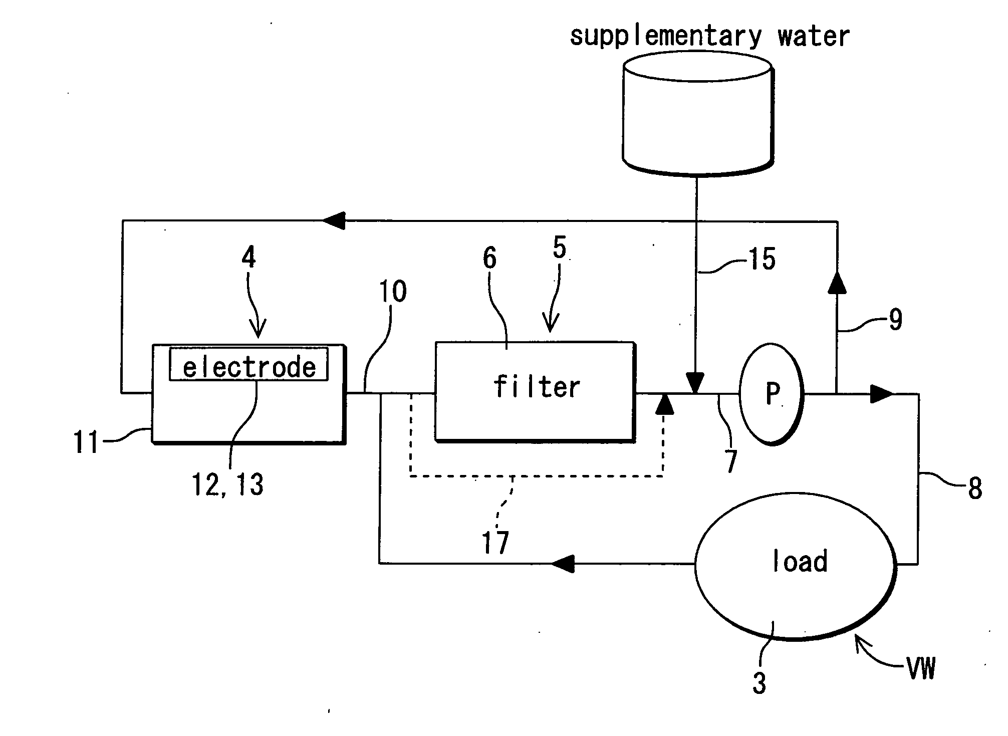
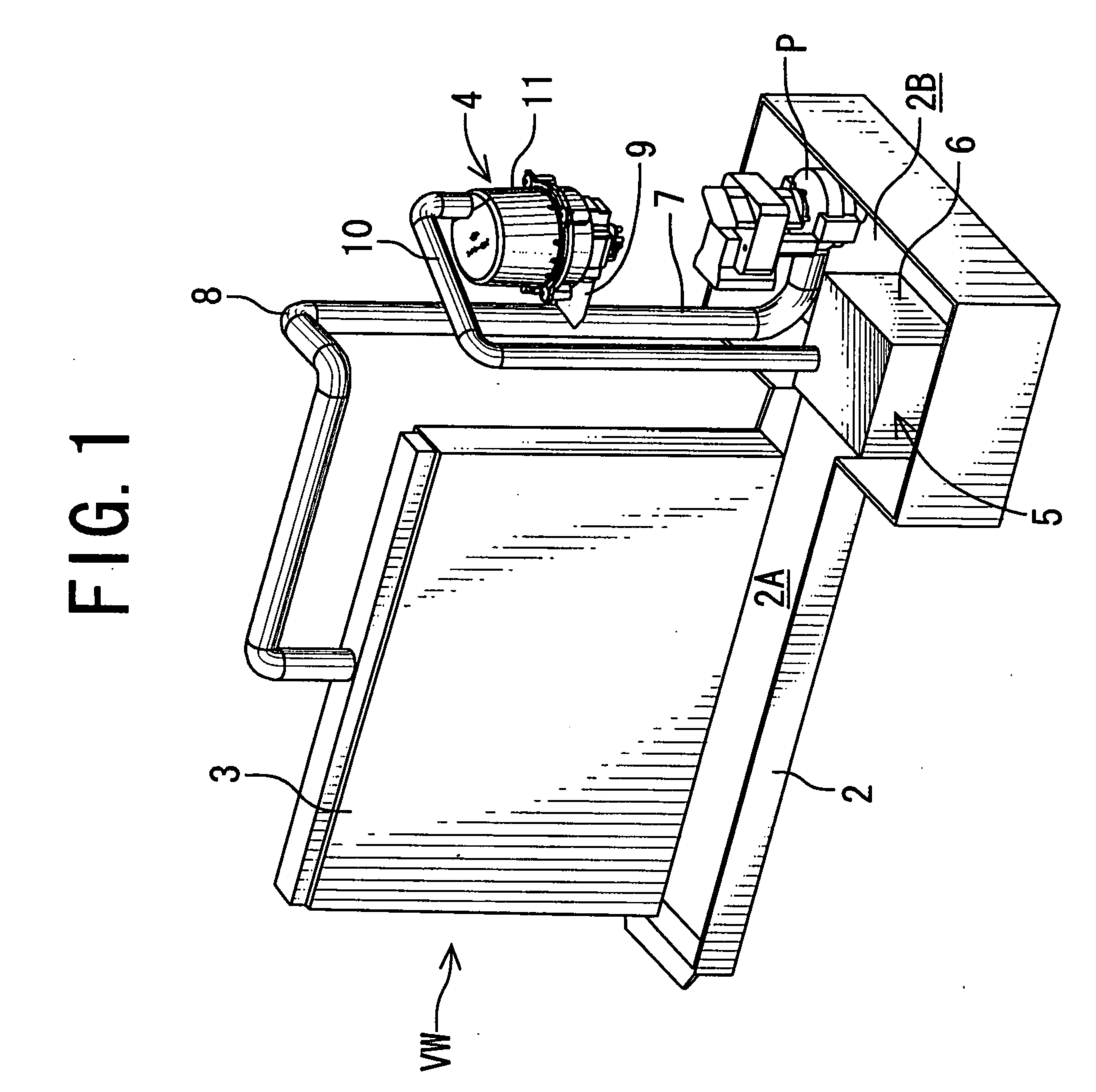
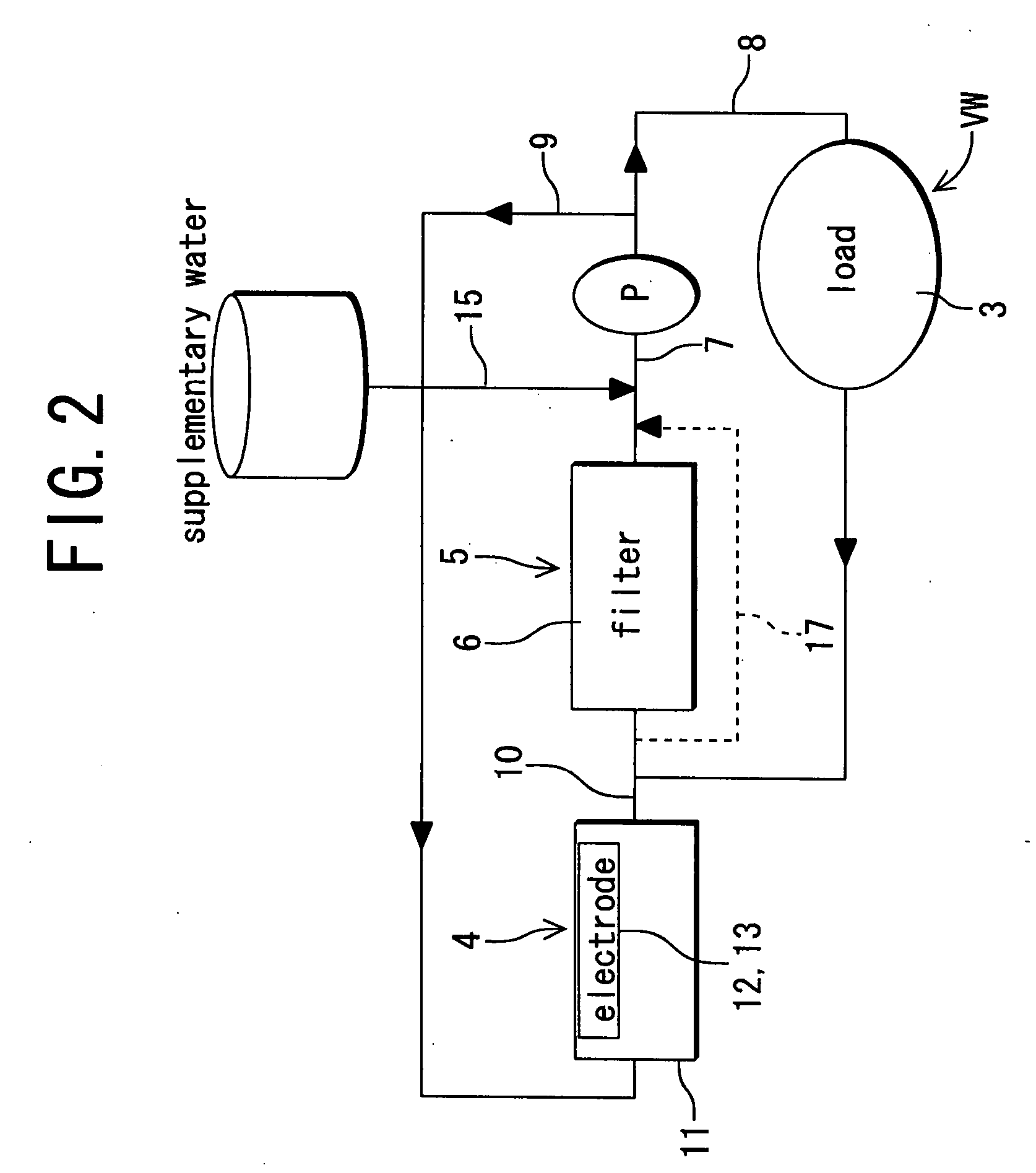
[0027]FIG. 1 shows a schematic constitution diagram of a scale collection system according to one embodiment of the present invention, and FIG. 2 shows a system diagram of the scale collection system shown in FIG. 1, respectively. In the present embodiment, the scale collection system of the present invention is applied to an air bacteria removal device VW. Therefore, a load of the present invention corresponds to an element of the air bacteria removal device VW.

[0028] The air bacteria removal device VW of the present embodiment includes a water reception tray 2 as a water storage section, an element 3 (corresponding to the load of the present invention) disposed on an upper surface of this water reception tray 2, an electrolytic cell 11, electrolytic treatment means 4 including a pair of electrodes 12, 13 (the electrodes are not shown in FIG. 1) and the like, scale collection means 5 disposed on a downstream side (an outlet side) of the electrolytic treatment means 4, and a pump P...

embodiment 2

[0050] Next, a scale collection system of another embodiment (a second embodiment) will be described with reference to FIG. 3. In the embodiment, the scale collection system is applied to an air bacteria removal device VW in the same manner as in Embodiment 1. FIG. 3 is a system diagram of the scale collection system of the present embodiment. It is to be noted that in FIG. 3, components denoted with the same reference numerals as those of FIGS. 1 and 2 produce similar effects and perform functions, and hence description thereof is omitted here.

[0051] In FIG. 3, reference numeral 20 denotes a resolving catalyst as hypochlorous acid resolving means. The resolving catalyst 20 of the present embodiment includes a catalyst which resolves hypochlorous acid in the for-treatment water, and is disposed along a pipe 22. The pipe 22 is one of pipes branched from a pipe 9A, one end of the pipe branched from the pipe 9A extends via the pipe 22, and the other end of the pipe is connected to a m...

embodiment 3

[0069] It is to be noted that in a case where a thermal catalyst such as nickel oxide is used as a resolving catalyst 20, that is, a catalyst is used which does not resolve hypochlorous acid in for-treatment water at ordinary temperature and which is heated to a predetermined temperature to perform a catalyst function and resolve hypochlorous acid in the for-treatment water, unlike Embodiment 2, the pipe 22 and the three-way valve 25 are not disposed. As shown in FIG. 6, the resolving catalyst 20 can be interposed along a pipe 9. In this case, heating means (e.g., a heater 27) capable of heating the resolving catalyst 20 to the predetermined temperature is attached to the resolving catalyst 20. It is to be noted that in a case where nickel oxide is used as the resolving catalyst 20, since the catalyst is heated at 40° C. to 70° C. to perform a resolving function, energization of the heater 27 needs to be controlled so that nickel oxide is heated at a temperature of 40° C. to 70° C. ...


PUM

PropertyMeasurementUnit
temperatureaaaaaaaaaa
wettabilityaaaaaaaaaa
polarityaaaaaaaaaa

Abstract

An object of the present invention is to provide a scale removal system capable of effectively avoiding a disadvantage that a scale is deposited on electrodes and a load, the system includes at least a pair of electrodes which are submerged into for-treatment water to electrochemically treat the for-treatment water, and a scale collection unit (a filter) disposed on a downstream side of the electrodes, the for-treatment water passed through the filter is split into flows, one flow is supplied to the load, then combined with the for-treatment water from the electrodes and returned to an inlet side of the scale collection unit, and the other flow is returned to an inlet side of the electrodes.

Description

BACKGROUND OF THE INVENTION [0001] The present invention relates to a system to remove a scale from water to be treated (hereinafter “water to be treated” will be referred to as “for-treatment water”). [0002] Heretofore, for a purpose of removal of microorganism viruses, bacteria and the like, a device is proposed in which for-treatment water is electrochemically treated to produce electrolytic water, and the water is supplied to a load to remove the bacteria and the like. For example, in an air bacteria removal device, the for-treatment water is electrochemically treated to produce the electrolytic water by electrolytic treatment means including a pair of electrodes, this electrolytic water is supplied to an element (a gas-liquid contact member) as a load to bring the water into contact with air in a bacteria removal space which is circulated through the element, whereby the bacteria are removed from the air in the bacteria removal space. [0003] However, when the for-treatment wate...

Claims


Application Information

Patent Timeline
Patent Type & Authority Applications(United States)
IPC IPC(8): C25F1/04C25B9/06C25B9/17
CPCC02F1/4602C02F1/46104C02F2303/04C02F5/00C02F1/4674C02F1/467C02F1/46
Inventor YAMAMOTO, TETSUYAKOIZUMI, TOMOHITORAKUMA, TSUYOSHIUMEZAWA, HIROYUKIYAMAMOTO, HIROSHIKOBAYASHI, HIROYUKIFUKUSHIMA, TOSHIOUSUI, HIROAKIARAKAWA, TOORU
Owner SANYO ELECTRIC CO LTD
Why Eureka
Try Eureka