Permanent-magnet reluctance electrical rotary machine

a permanent magnet and electrical rotary machine technology, applied in the direction of dynamo-electric machines, magnetic circuit rotating parts, magnetic circuit shape/form/construction, etc., can solve the problems of harmonic loss, increase in iron loss, and significant reduction in efficiency, and achieve the effect of reducing the number of rotary machines

Active Publication Date: 2008-04-24
KK TOSHIBA +1
View PDF16 Cites 46 Cited by
  • Summary
  • Abstract
  • Description
  • Claims
  • Application Information

AI Technical Summary

Benefits of technology

[0017]The present invention has been devised to solve such problems in the related art, and it is an object of the present invention to provide a permanent-magnet reluctance electrical rotary machine allowing motor losses to be reduced with maintained degrees of rotor strength to endure high revolution speeds, thereby affording an increased efficiency and a controlled heat dissipation of electrical rotary machine, allowing for high torque, high power, and enhanced reliability in a limited space.
[0029]According to the sixth aspect of the present invention, an optimal selection is made of rotor pole number and stator slot number, allowing for provision of most favorable motor characteristics (torque, loss, and stress).

Problems solved by technology

However, in the related art shown in FIG. 3, the permanent-magnet reluctance electrical rotary machine employs permanent magnet positioning projections 4 for supporting permanent magnets 2 with secured degrees of rotor core strength to thereby afford an increased power and higher speed, and may achieve the higher speed with an increase in iron loss, harmonic loss or such, and a significant reduction in efficiency.
Further, with an increased density of loss (density of heat dissipation) due to miniaturization and increased power, the electrical rotary machine may undergo a significant temperature rise involving a deteriorated insulation, thermal demagnetization of permanent magnets, and the like, with a reduced reliability, as a problem.
As for the rotor shown in FIG. 4, the cavity 9 (interpolar air gap) disposed at an outer circumferential side of permanent magnets 2 has its configuration and dimensions numerically limited to thereby afford high torque, and may have among others a high-speed revolution range achieved by a configuration and dimensions suitable for high torque and different from those meeting low-loss requirements, and may fail to successfully control motor losses, involving a reduced efficiency and lower reliability due to temperature rise, as a problem.

Method used


Image

  • Permanent-magnet reluctance electrical rotary machine
  • Permanent-magnet reluctance electrical rotary machine
  • Permanent-magnet reluctance electrical rotary machine

Examples


first embodiment

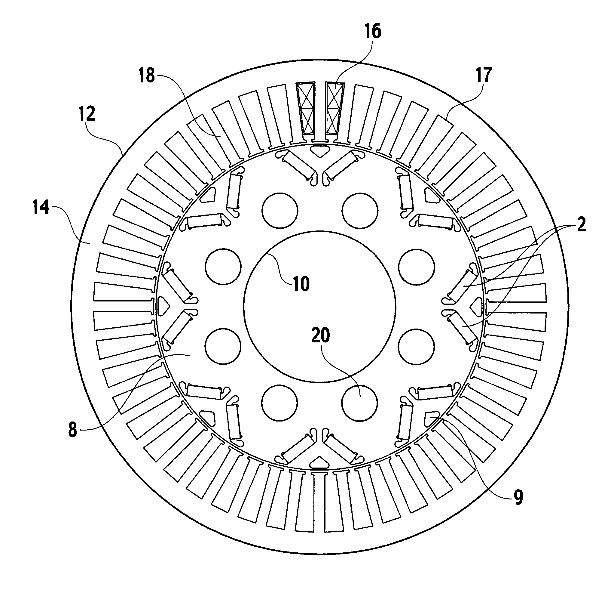
[0044]Description is now made of a first embodiment of the present invention. FIG. 5 is a diametrical sectional view of a permanent-magnet reluctance electrical rotary machine according to the first embodiment, and FIG. 6, an enlarged diametrical sectional view of the permanent-magnet reluctance electrical rotary machine according to the first embodiment. Like or equivalent elements to FIG. 1 to FIG. 4 are designated by like reference characters, eliminating redundancy.

[0045]Description is now made of configuration of the present embodiment. A stator 12 has a stator core 14 and a combination of armature windings 16. The stator core 14 is made up by laminations of magnetic steel sheets, and has at their inner circumferential sides a set of stator slots 17 for accommodating armature windings 16, and a set of stator teeth 18 fronting a rotor 10. The stator slots are forty-eight in total. The rotor 10, installed inside the stator 12, has a rotor core 8, a plurality of permanent magnets ...

second embodiment

[0061]Description is now made of a second embodiment of the present invention. FIG. 10 is an enlarged diametrical sectional view of a permanent-magnet reluctance electrical rotary machine according to the second embodiment. Like or equivalent elements to FIG. 5 or FIG. 6 are designated by like reference characters, eliminating redundancy.

[0062]For basic configuration, the second embodiment is identical to the first embodiment. A magnet angle α is now defined as an open angle made by an axial center of a rotor and vertexes of corners at rotor outer-circumferential sides of two permanent magnets 2 arranged in a V-form. The magnets 2 are arranged so as to meet a relationship by which the magnet angle α is set within a range of 82 degrees or more and 92 degrees or less in terms of an electric angle.

[0063]The electric angle is defined relative to an angle between N pole and S pole neighboring each other to be electrical π [rad]. Letting P be a pole number, the electric angle has a value ...


PUM


Abstract

For an electrical reluctance rotary machine, a stator has a winding as an armature, and a rotor has permanent magnet implanting slots provided in a rotor core at lateral sides magnetic poles configured to produce reluctance torque along directions of magnetic flux passing through the magnetic poles to produce reluctance torque, and permanent magnets inserted in the permanent magnet implanting slots so as to cancel magnetic flux of the armature intersecting that magnetic flux, to control a magnetic field leaking at ends of the magnetic poles, having circumferential magnetic concavo-convex. The electrical reluctance rotary machine is configured to meet a relationship, such that1.6≤P×WpmR≤1.9where Wpm [mm] is a width of permanent magnet, R [mm] is an outer-diametrical radius of the rotor, and P is the number of poles.

Description

CROSS REFERENCE TO RELATED APPLICATION[0001]The present application claims the benefit of priority under 35 U.S.C. § 119 to Japanese Patent Application No. 2006-286366, filed on, Oct. 20, 2006, of which the contents are incorporated herein by reference.BACKGROUND OF THE INVENTION[0002]1. Field of the Invention[0003]The present invention relates to an electrical rotary machine of a permanent magnet type in complex with permanent magnets, and particularly, to a permanent magnet type electrical rotary machine with high torque, high power, and enhanced reliability in a limited space.[0004]2. Description of Related Art[0005]Recent years have observed remarkable researches and developments in the art of permanent magnet, having developed permanent magnets with a high magnetic energy product, involving advancements in miniaturization and power enhancement of electrical rotary machines. In particular, for electrical rotary machines having such applications to vehicles as addressed to hybrid...

Claims


Application Information

Patent Timeline
Patent Type & Authority Applications(United States)
IPC IPC(8): H02K21/12H02K1/27H02K1/28
CPCH02K1/2766H02K1/246
Inventor TAKAHASHI, NORIOSAKAI, KAZUTOARATA, MASANORIHASHIBA, YUTAKAITO, WATARUMOCHIZUKI, MOTOYASUTAKABATAKE, MIKIOMATSUBARA, MASAKATSUHANAI, TAKASHI
Owner KK TOSHIBA
Why Eureka
Try Eureka