Photobleaching by high power pulses

Inactive Publication Date: 2008-04-24
CHEMIMAGE TECH
View PDF4 Cites 16 Cited by
  • Summary
  • Abstract
  • Description
  • Claims
  • Application Information

AI Technical Summary

Benefits of technology

[0010]The present disclosure describes various embodiments of a pulse photobleaching methodology wherein a monochromatic illumination (e.g., laser illumination) having a higher power intensity (photobleaching power) just below the photodamage threshold of a luminescent sample is initially used to significantly attenuate sample luminescence without photothermally destroying the sample material. Thereafter, the laser power density may be reduced to a significantly lower level (analytical power level) to carry out spectroscopic measurements (e.g., collection of Raman scattered photons) on the sample. In one em

Problems solved by technology

A significant impediment to the acquisition of Raman spectra, particularly of samples of biological materials or industrial che

Method used


Image

  • Photobleaching by high power pulses
  • Photobleaching by high power pulses
  • Photobleaching by high power pulses

Examples


Embodiment Construction

[0021]The accompanying figures and the description that follows set forth the present disclosure in embodiments of the present disclosure. However, it is contemplated that persons generally familiar with spectral measurements, operation and maintenance of optical instruments (including spectroscopic instruments), or optical spectroscopy will be able to apply the teachings of the present disclosure in other contexts by modification of certain details. Accordingly, the figures and description are not to be taken as restrictive of the scope of the present disclosure, but are to be understood as broad and general teachings. In the discussion herein, when any numerical range of values is referred or suggested, such range is understood to include each and every member and / or fraction between the stated range of minimum and maximum.

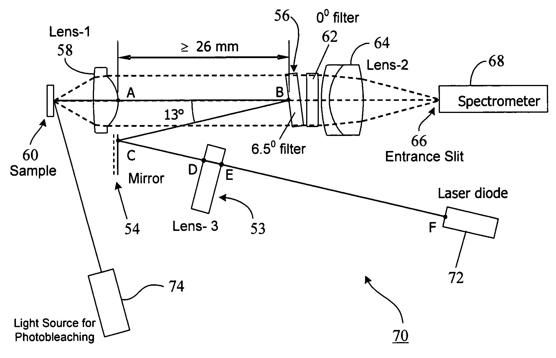
[0022]In the photobleaching approach according to one embodiment of the present disclosure, a higher laser power illumination (than that used for routine spectr...


PUM


Abstract

A pulse photobleaching methodology wherein a monochromatic illumination (e.g., laser illumination) having a higher power intensity (photobleaching power) just below the photodamage threshold of a luminescent sample is initially used to significantly attenuate sample luminescence without photothermally destroying the sample material. Thereafter, the laser power density may be reduced to a significantly lower level (analytical power level) to carry out spectroscopic measurements (e.g., collection of Raman scattered photons) on the sample. In one embodiment, the laser illumination wavelength remains the same despite changes in laser power intensity. Some figures-of-merit may be computed from optical measurements made at the analytical power level to guide the photobleaching process. Sample-dependent combinations of laser power density and short exposure times may be obtained to significantly expedite photobleaching to assist in collection of sample spectral data in the field without a long wait. Portable spectroscopy systems employing pulse photobleaching may be devised for expeditious collection of spectral data from luminescent samples in the field.

Description

REFERENCE TO RELATED APPLICATION[0001]The disclosure in the present application claims priority benefit of the U.S. Provisional Application No. 60 / 852,766, titled “Photobleaching by High Power Pulses,” and filed on Oct. 19, 2006.BACKGROUND[0002]1. Field of the Disclosure[0003]The present disclosure generally relates to photobleaching of luminescent materials and, more particularly, to a system and method of photobleaching using a fixed-wavelength, variable intensity laser illumination.[0004]2. Brief Description of Related Art[0005]Raman spectroscopy may be used for the identification of biological and chemical materials. A significant impediment to the acquisition of Raman spectra, particularly of samples of biological materials or industrial chemical mixtures / solutions, is the luminescence in the sample generated by the illumination used to generate the Raman scattering. This occurs when any or all of the material components being illuminated absorb light at the monochromatic wavel...

Claims


Application Information

Patent Timeline
IPC IPC(8): G01N21/00G21G5/00G01J1/00G01J3/28G01J3/30G01J3/44
CPCG01J3/10G01N21/65G01N21/274G01J3/44
Inventor TUSCHEL, DAVIDBANGALORE, ARJUN
Owner CHEMIMAGE TECH
Why Eureka
Try Eureka