Echelle Spectometer with Improved Use of the Detector by Means of Two Spectrometer Arrangements

a spectrometer and detector technology, applied in the field of spectrometer assembly with a spectrometer, can solve the problems of loss of total loss at the additional optical components, and loss of unambiguous separation of orders, and achieve the effect of small light throughput, high light throughput, and high light throughpu

Active Publication Date: 2008-04-24
LEIBNIZ - INSTITUT FUER ANALYTISCHE WISSENSCHAFTEN ISAS
View PDF3 Cites 12 Cited by
  • Summary
  • Abstract
  • Description
  • Claims
  • Application Information

AI Technical Summary

Benefits of technology

[0015] By using additional optical components in a separate light path the spectrum can be divided into two spectral ranges. The optical components, i.e. dispersion elements, mirrors, entrance slit width etc. can be individually adapted to the measurement task. In such a way a small throughput of light for wavelength ranges with high intensity can be chosen and a high throughput of light for wavelength ranges with low intensity can be chosen. Thereby the radiation on the detector can be better adapted to its dynamic range. Intensive lines can be measured simultaneously with weak lines. Furthermore, the two spectra generated by the different spectrometer assemblies in the common imaging plane can be detected by the same detector area so that the overall outer

Problems solved by technology

On the other hand, there are overall losses at the additional optical components.
There are correspondingly high transmission losses with simultaneous smaller resulting dispersion.
However, it is a disadvantage that the unambiguousn

Method used


Image

  • Echelle Spectometer with Improved Use of the Detector by Means of Two Spectrometer Arrangements
  • Echelle Spectometer with Improved Use of the Detector by Means of Two Spectrometer Arrangements
  • Echelle Spectometer with Improved Use of the Detector by Means of Two Spectrometer Arrangements

Examples


Embodiment Construction

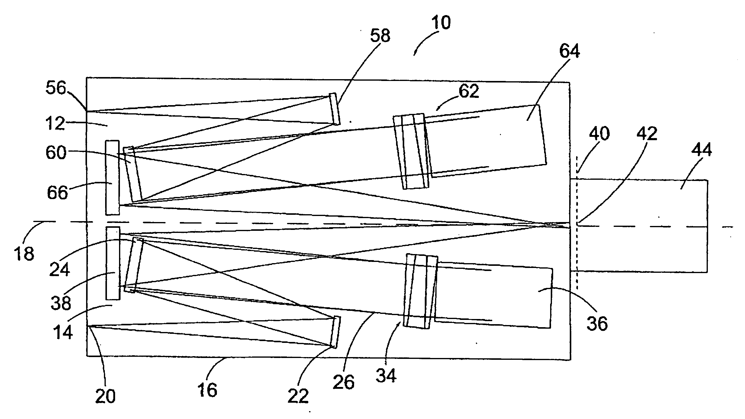
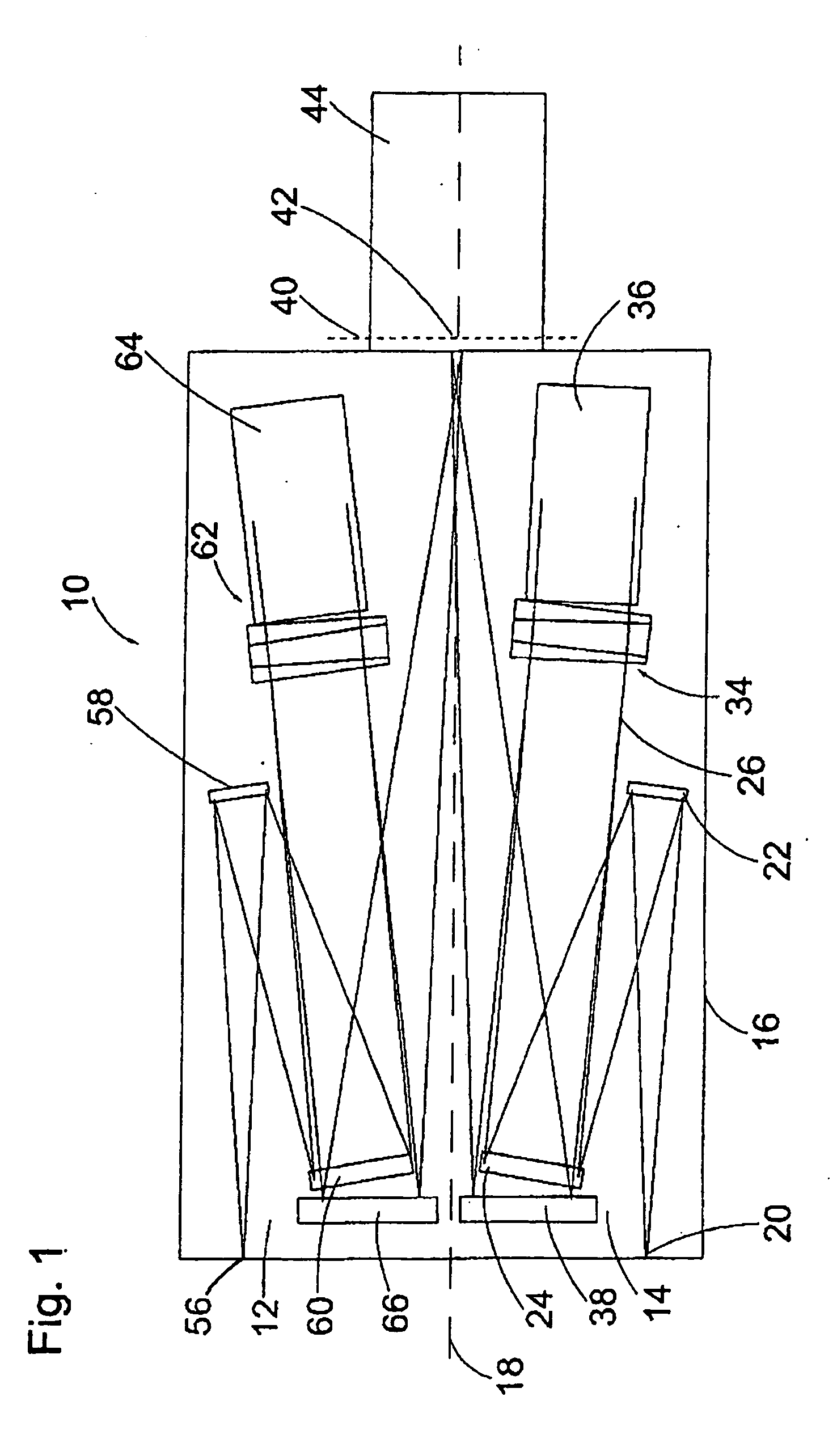
[0031] Numeral 10 generally designates a spectrometer assembly in FIG. 1. The spectrometer assembly 10 comprises two spectrometers 12 and 14 disposed in a common housing 16. The components of the spectrometer 12 and 14 are mirror-inverted with respect to the plane 18. For simplicity only one of the spectrometers is, therefore, described in detail.

[0032] Radiation enters the spectrometer through an entrance slit 20. The incident radiation meets the plane mirror 22. The radiation is reflected at the plane mirror 22 in the direction of the collimator mirror 24. The collimator mirror 24 is a spherical mirror used for parallelizing divergent radiation. The parallel bundle 26 runs through a prism 34. An Echelle grating 36 is arranged behind the prism.

[0033] The dispersion direction of the Echelle grating 36 extends in a plane perpendicular to the illustration plane in FIG. 1. The grooves of the Echelle grating lay in the illustration plane essentially from top to bottom in FIG. 1. The E...


PUM


Abstract

The invention relates to a spectrometer arrangement (10) comprising a spectrometer (14) for producing a spectrum of a first wavelength range of radiation from a radiation source on a detector (42). Said arrangement also comprises: an Echelle grating (36) for the spectral decomposition of the radiation penetrating the spectrometer arrangement (10) in a main dispersion direction (46); a dispersing element (34) for separating the degrees by means of spectral decomposition of the radiation in a transversal dispersion direction (48) which forms an angle with the main dispersion direction of the Echelle grating (36), in such a way that a two-dimensional spectrum (50) can be produced with a plurality of separated degrees (52); an imaging optical element (24, 38) for imaging the radiation penetrating through an inlet gap (20) into the spectrometer arrangement (10), in an image plane (40); and a surface detector (42) comprising a two dimensional arrangement of a plurality of detector elements in the image plane (40). The inventive arrangement is characterised in that another spectrometer (12) comprising at least one other dispersing element (64) and another imaging optical element (60,66) is provided in order to produce a spectrum (68) of a second wavelength range of radiation, which is different from the first wavelength range, from a radiation source on the same detector (42). The spectra can be spatially or temporally separated on the detector.

Description

TECHNICAL FIELD [0001] The invention relates to a spectrometer assembly with a spectrometer for generating a radiation spectrum in a first wavelength range of a light source on a detector comprising: [0002] (a) an Echelle grating for spectrally dispersing radiation entering the spectrometer assembly in a main dispersion direction; [0003] (b) a dispersion element for separating the orders by means of spectrally dispersing the radiation in a lateral dispersion direction forming an angle with the main dispersion direction of the Echelle grating adapted to generate a two dimensional spectrum with a plurality of separated orders; [0004] (c) an imaging optical system for imaging the radiation entering through an entrance slit into the spectrometer assembly in an imaging plane and [0005] (d) a detector array with a two-dimensional arrangement of a plurality of detector elements in the imaging plane. [0006] Gratings with a stair-like cross section (Echelle (french)=stairs) are used in such ...

Claims


Application Information

Patent Timeline
IPC IPC(8): G01J3/28G01J3/02G01J3/08G01J3/12G01J3/18
CPCG01J3/02G01J3/0202G01J3/0208G01J3/021G01J3/0232G01J3/2803G01J3/0286G01J3/0294G01J3/08G01J3/12G01J3/1809G01J3/0237
Inventor BECKER-ROSS, HELMUTFLOREK, STEFANWESEMANN, GUNTEROKRUSS, MICHAEL
Owner LEIBNIZ - INSTITUT FUER ANALYTISCHE WISSENSCHAFTEN ISAS
Why Eureka
Try Eureka