Dual illumination anisotropic light emitting device
an anisotropic light and light emitting technology, applied in the field of electroluminescent signs, can solve problems such as the problem of increasing the visible speckle contrast of the sign, and achieve the effects of improving the visible speckle contrast, efficient directivity, and improving the electroluminescent sign
- Summary
- Abstract
- Description
- Claims
- Application Information
AI Technical Summary
Benefits of technology
Problems solved by technology
Method used
Image
Examples
example 1
[0106] An enhanced electroluminescent sign in accordance with the present invention, i.e., as illustrated in FIG. 11, has increased spatial luminance uniformity, increased optical efficiency and is of low production cost. A 16″×20″ direct-lit light box sign (UltraThin Light Up Display from Bowman Displays) is used as a benchmark for comparison with the enhanced electroluminescent sign of this invention. The spatial luminance uniformity is measured at 0.5 cm intervals on either side of a region directly above the T8 fluorescent lamp in the white light box with the included standard symmetric diffuser film (Sample STANDARD) with a Minolta CS-100 spectrophotometer. The angular luminance profile is measured at a location directly above a fluorescent bulb with the standard symmetric diffuser film with a Minolta CS-100 luminance and tristimulous spot meter at varying 5 degree angular positions.
[0107] A light scattering film with anisotropic scattering profile was prepared by blending and...
example 2
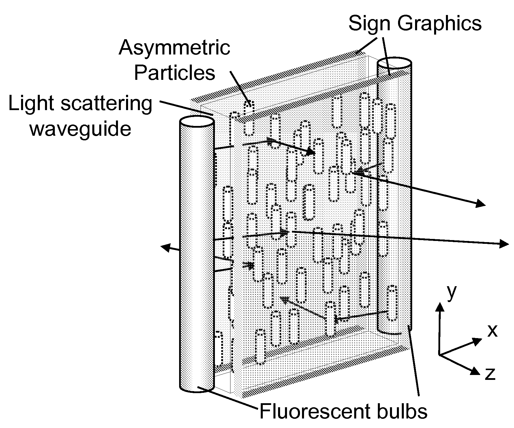
[0109] An enhanced electroluminescent sign in accordance with the present invention can be produced as described in FIG. 8, that has increased spatial luminance uniformity, increased optical efficiency, reduced speckle and lower costs of production. This is due in part to the use of the volumetric anisotropic scattering region within the waveguide to more efficiently control the light scattering. A light diffusing waveguide containing light scattering particles in a host matrix material is created by extruding, casting or coating, the mixture containing particles. The particle chosen may be a polystyrene bead of diameter 5 μm in the minor axis and 20 μm in the major axis dispersed at 10% concentration in a host matrix of acrylic. Other choices of particles and host matrix may provide equivalent performance. Asymmetry and alignment of the asymmetry can be created by stretching or extrusion processes. The resulting material suitable for waveguiding light contains asymmetric particles ...
example 3
[0110] An enhanced electroluminescent sign, in accordance with the present invention, can be produced as described in FIG. 11, that is designed to have increased spatial luminance uniformity, increased optical efficiency, reduced speckle and lower costs of production. This is due in part to the use of the volumetric anisotropic scattering element more efficiently controls the light scattering. A light diffusing film containing light scattering particles in a host matrix material is created by extruding, casting or coating, the mixture containing particles. The particle chosen may be a polystyrene bead of diameter 5 μm in the minor axis and 20 μm in the major axis dispersed at 10% concentration in a host matrix of acrylic. Other choices of particles and host matrix can provide equivalent performance. Asymmetry and alignment of the asymmetry can be created by stretching or extrusion processes. The resulting film suitable for diffusing light contains asymmetric particles and is placed ...
PUM
 Abstract
Description
Claims
Application Information
 - R&D
- Intellectual Property
- Life Sciences
- Materials
- Tech Scout
- Unparalleled Data Quality
- Higher Quality Content
- 60% Fewer Hallucinations
Browse by: Latest US Patents, China's latest patents, Technical Efficacy Thesaurus, Application Domain, Technology Topic, Popular Technical Reports.
© 2025 PatSnap. All rights reserved.Legal|Privacy policy|Modern Slavery Act Transparency Statement|Sitemap|About US| Contact US: help@patsnap.com


