Two-Stroke Internal Combustion Engine

a two-stroke, internal combustion technology, applied in the direction of combustion engines, reciprocating piston engines, positive displacement engines, etc., can solve the problems of difficult to take effective measures to reduce the emissions of two-stroke engines, and achieve the effect of preventing the phenomenon of “blow-by” and reducing the content of harmful emissions

Inactive Publication Date: 2008-05-01
YAMABIKO CORP
View PDF3 Cites 5 Cited by
  • Summary
  • Abstract
  • Description
  • Claims
  • Application Information

AI Technical Summary

Benefits of technology

[0019]In the above two-stroke internal combustion engine (1), the second scavenging port (13) located remoter from the exhaust port (11) are opened earlier to introduce the air (A) into the combustion chamber (6), and the first scavenging ports (12) located nearer to the exhaust port (11) are opened later to introduce the air-fuel mixture (M) into the combustion chamber (6) in each scavenging stroke. Thus, the air (A) introduced earlier into the combustion chamber (6) results in enveloping the air-fuel mixture (M) introduced later into the combustion chamber (6) through the first scavenging ports (12) that are opened later than the second scavenging ports (13). Therefore, it is possible to prevent that the air-fuel mixture (M) introduced into the combustion chamber (6) and having not burned is discharged to the exhaust port (11). In other words, the so-called “blow-by” phenomenon is prevented. Prevention of the blow-by of air-fuel mixture, which is the problem in the two-stroke internal combustion engines, makes it possible to reduce the content of harmful emissions in exhaust gas (E).

Problems solved by technology

As such, the two-stroke engines are configured to scavenge the combustion chamber by using flows of air-fuel mixture, and therefore involve the problem of “blow-by”.
This “blow-by” phenomenon makes it difficult to take effective measures for emissions cut of two-stroke engines.

Method used


Image

  • Two-Stroke Internal Combustion Engine
  • Two-Stroke Internal Combustion Engine
  • Two-Stroke Internal Combustion Engine

Examples


Embodiment Construction

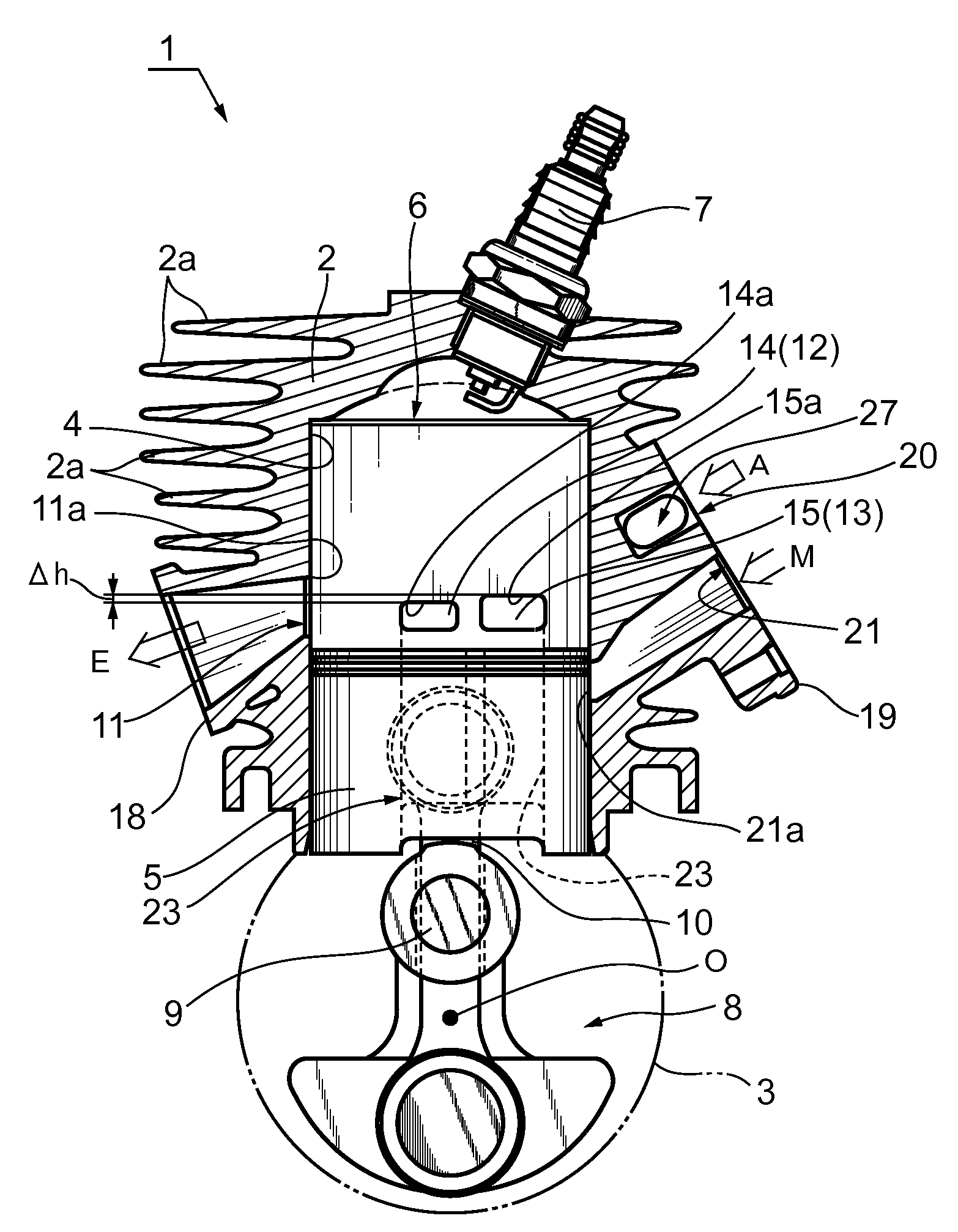
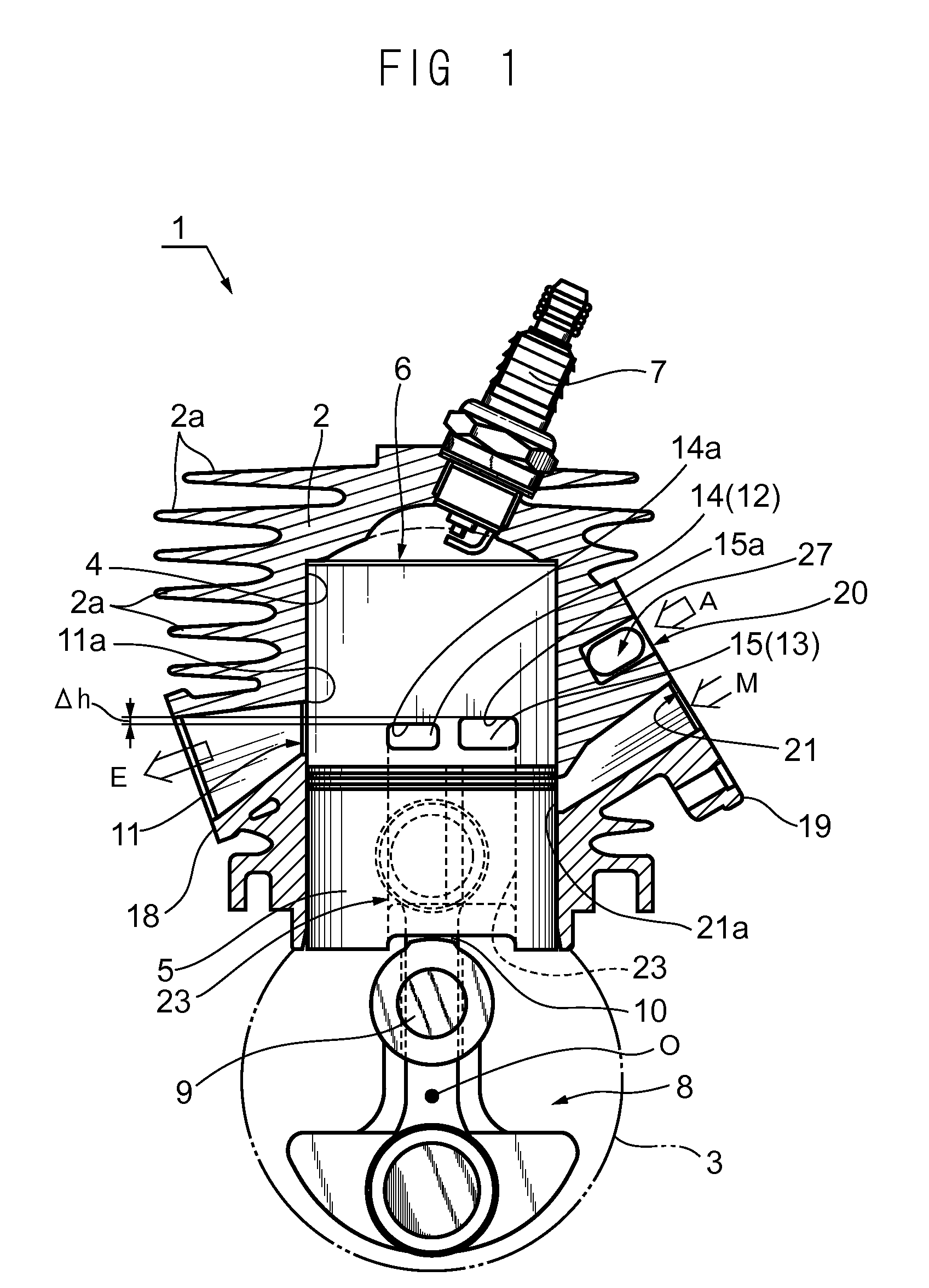
[0032]A two-stroke internal combustion engine according to an embodiment of the present invention and some changes thereof are explained below with reference to the accompanying drawings. FIG. 1 and other drawings illustrate an example to be brought into operation as a single-cylinder. The two-stroke internal combustion engine generally designated with reference numeral 1 is a four-flow scavenging, air-cooled, compact two-stroke gasoline engine used in portable power working machines.

[0033]As shown in FIG. 1, the engine 1 includes a cylinder block 2 having cooling fins 2a, and a crank case 3 connected to the bottom of the cylinder block 2. A cylinder bore 4 formed in the cylinder block 2 fittingly receives a piston 5 to permit its reciprocal movement therein. The piston 5 defines a combustion chamber 6 in the cylinder bore 4.

[0034]The combustion chamber 6 has a squish-dome (hemispherical) shape. An ignition plug 7 is disposed at the top of the combustion chamber 6. In a crank chambe...


PUM


Abstract

A cylinder bore (4) of a two-stroke internal combustion engine (1) has first scavenging ports (12) and second scavenging ports (13) inside. The first scavenging ports (12) are nearer to an exhaust port (11) of the engine (1) than the second scavenging ports (13). In each scavenging stroke, the second scavenging ports (13) are opened earlier than the first scavenging ports (12) and introduce fuel-free air (A) from the second scavenging ports (13) into a combustion chamber (6). The first scavenging ports (12) are opened later and introduce an air-fuel mixture (M) pre-compressed in a crank chamber (8) into the same combustion chamber (6). Thus, harmful substances contained in exhaust gas discharged from the engine (1) are reduced.

Description

FIELD OF THE INVENTION[0001]The present invention generally relates to two-stroke internal combustion engines. More particularly, the present invention relates to such engines used as a power source of portable power working machines such as chain saws, hedge trimmers, brush cutters, and the like.BACKGROUND OF THE INVENTION[0002]Two-stroke gasoline engines have been used as a power source of portable power working machines such as hedge trimmers, brush cutters, chain saws or the like. In a two-stroke engine of this type, a combustion chamber is scavenged by a flow of air-fuel mixture pre-compressed in a crank chamber. More specifically, as the piston ascends, the air-fuel mixture is introduced into the crank chamber, and pre-compressed by the descending piston. Then, during the scavenging stroke, the pre-compressed air-fuel mixture is introduced into the combustion chamber to force waste combustion gas (exhaust gas) out of the combustion chamber and replace it.[0003]As such, the two...

Claims


Application Information

Patent Timeline
Patent Type & Authority Applications(United States)
IPC IPC(8): F01B7/14
CPCF02B2075/025F02B25/14
Inventor MOCHIZUKA, MITSUJIROMATSUO, KENTAROYAMAZAKI, TAKAHIROSATO, SHIGERU
Owner YAMABIKO CORP
Why Eureka
Try Eureka