Process for upgrading tar

a technology of tar and process, applied in the field of tar upgrading, can solve the problems of reducing the amount of valuable products such as light olefins, sct continues to be generated in quantities beyond the capacity of current technology to be efficiently utilized, and the sct tends to be incompatible with s

Active Publication Date: 2008-05-01
EXXONMOBIL CHEM PAT INC
View PDF19 Cites 52 Cited by
  • Summary
  • Abstract
  • Description
  • Claims
  • Application Information

AI Technical Summary

Problems solved by technology

SCT tends to be incompatible with other “virgin” (meaning it has not undergone any hydrocarbon conversion process such as FCC or steam cracking) products of the refinery pipestill upstream from the steam cracker.
One way to avoid production of SCT is to limit conversion of the pyrolysis feed, but this also reduces the amount of valuable products such as light olefins.
Despite these advances, there remains a problem that SCT continues to be generated in amounts beyond the capacity of current technology to be efficiently utilized.
However, steam cracker tar, even relatively low asphaltene steam cracker tar, is generally incompatible with fuel oil pools such as Bunker C fuel oil.
Onsite tar burning in site boilers is then preferred to avoid tar separation investment, but tighter emission regulations increasingly limit the amount that can be burned for this purpose.

Method used


Image

  • Process for upgrading tar
  • Process for upgrading tar
  • Process for upgrading tar

Examples


first embodiment

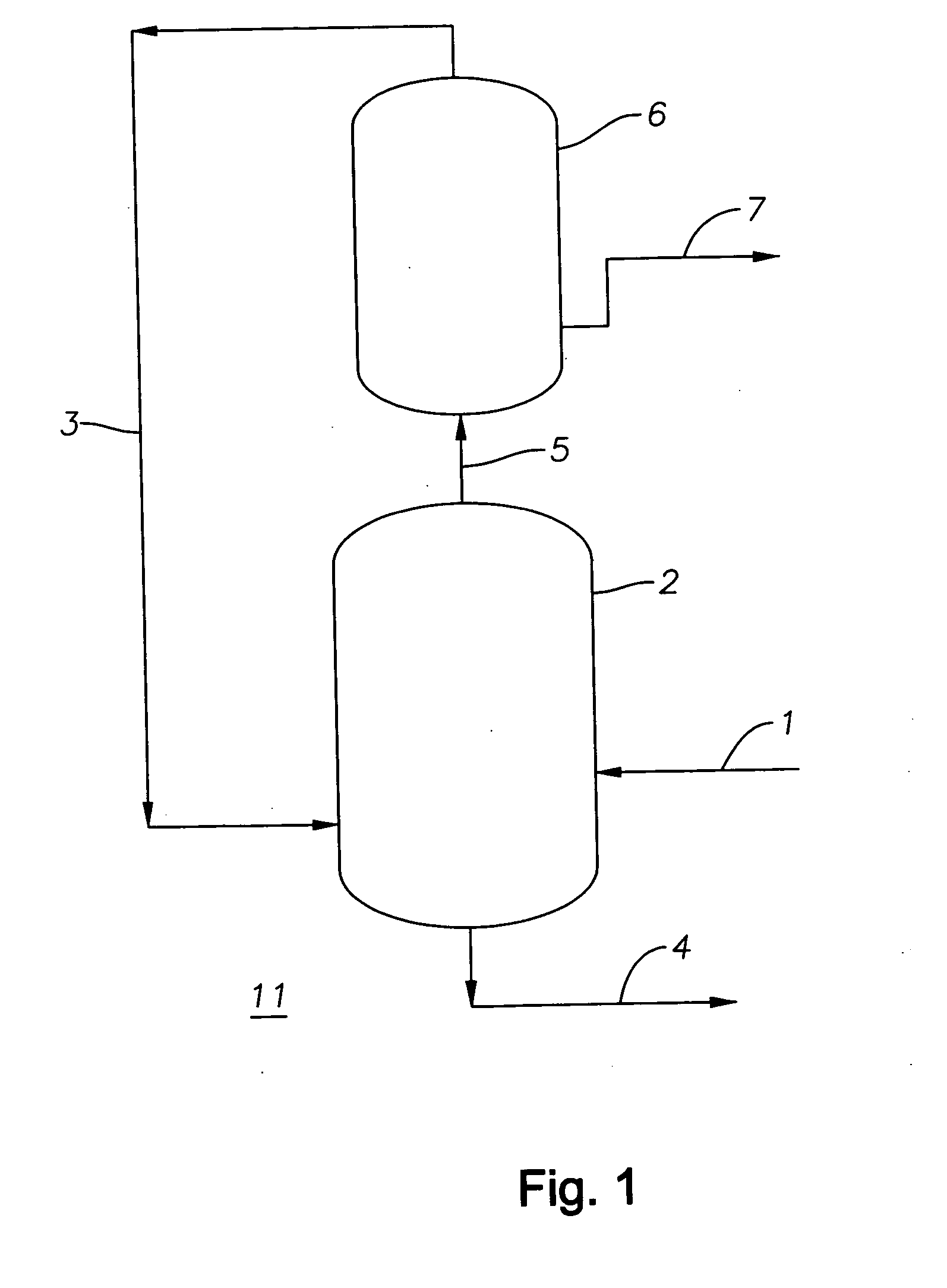
[0041]FIG. 1 is a simplified schematic flow diagram of the invention, showing a system 11 useful in a process for deasphalting tar. In FIG. 1, a feedstream comprising tar is provided through conduit 1 to the solvent deasphalter 2 from the primary fractionator downstream of a pyrolysis furnace.

[0042]The pyrolysis furnace along with the associated primary fractionator is not shown in the drawing but may be conventional or preferably the pyrolysis furnace has an integrated vapor / liquid separator, as described in U.S. Patent Applications 2004 / 0004022; 20040004027; 2004 / 0004028; 2005 / 0209495; 2005 / 0261530; 2005 / 0261531; 2005 / 0261532; 2005 / 0261533; 2005 / 0261534; 2005 / 0261535; 2005 / 0261536; 2005 / 0261537; and 2005 / 0261538; and in U.S. Pat. No. 6,632,351.

[0043]The feedstream provided through 1 is typically the bottoms product of the primary fractionator of a pyrolysis furnace, having a boiling point of 550° F.+ and including a fraction having a boiling point of 1000° F.+.

[0044]In the solvent...

second embodiment

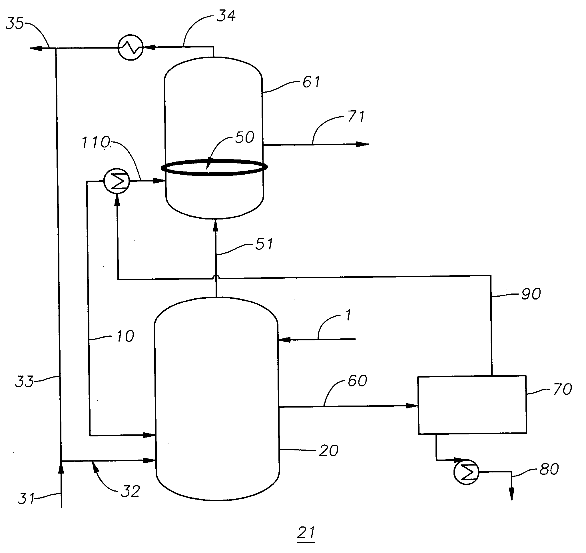
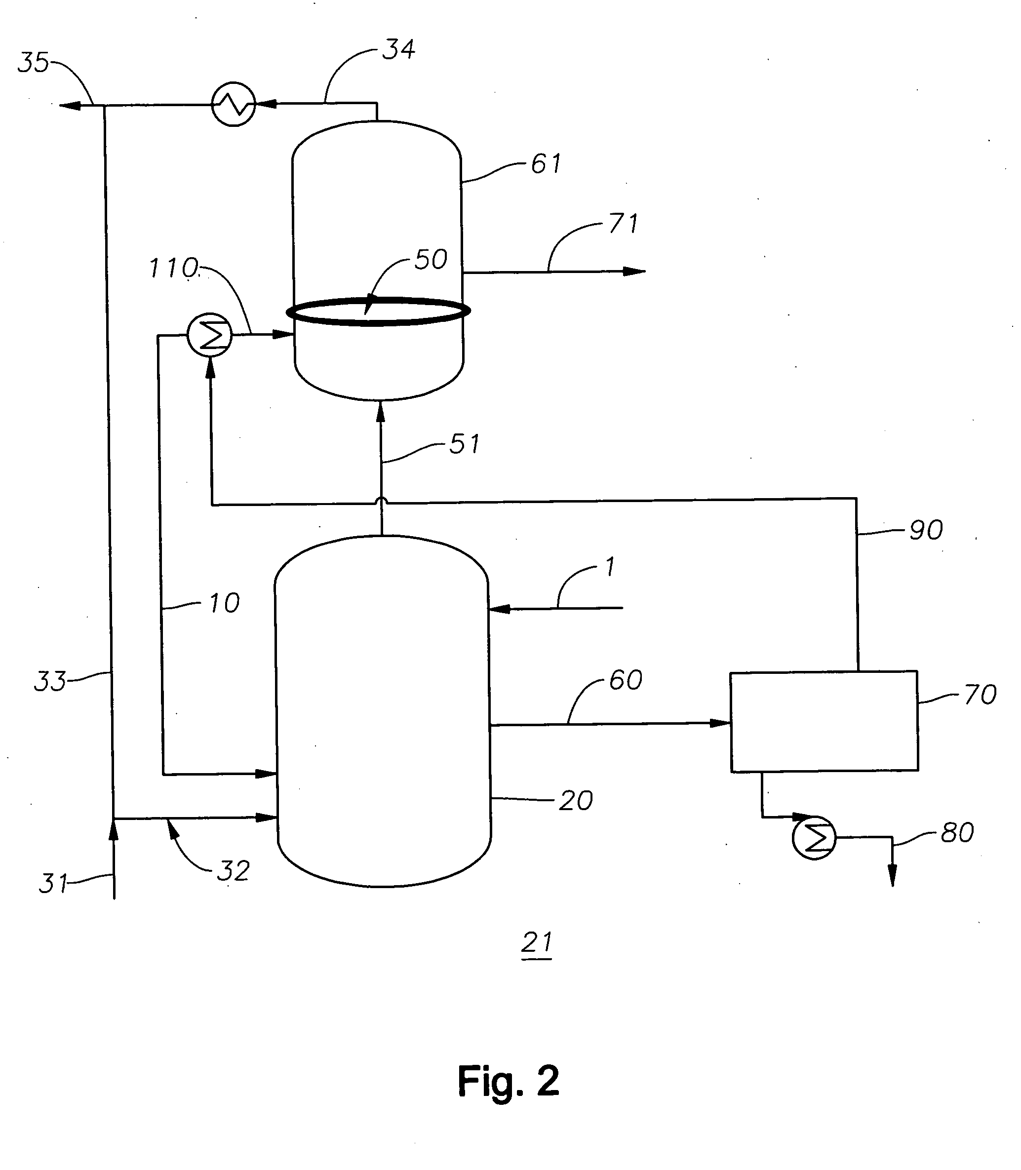
[0047]A more preferred embodiment is shown in FIG. 2, which is a simplified schematic flow diagram of the invention. In this embodiment, the process for deasphalting tar, using the deasphalting system 21, is integrated with the front end of at least one pyrolysis furnace (not shown in the figure) so that at least a portion of the feedstream to the pyrolysis furnace is used as the fluid in the fluid or solvent deasphalter and, after recovery in the said recovery facilities, may then be sent to the pyrolysis furnace such as by rejoining the fluid with the feedstream to the pyrolysis furnace, as discussed with respect to FIG. 2, to generate, by way of example, light olefins.

[0048]In FIG. 2, a slipstream (or portion) is taken off in conduit 32 from a feedstream to one or more pyrolysis furnace(s) (not shown) fed by conduit 35, and used as solvent in the solvent deasphalter apparatus 20, also fed with the bottoms product comprising tar through conduit 1 (as in FIG. 1) from one or more pr...


PUM

PropertyMeasurementUnit
wt %aaaaaaaaaa
temperaturesaaaaaaaaaa
boiling pointaaaaaaaaaa

Abstract

A feedstream comprising tar is feed to a solvent deasphalter wherein it is contacted with a deasphalting solvent or fluid to produce a composition comprising a mixture or slurry of solvent containing a soluble portion of the tar, and a heavy tar fraction comprising the insoluble portion of the tar. These fractions may be separated in the deasphalter apparatus, such as by gravity settling wherein the heavy tar fraction is taken off as bottoms, and the solvent-soluble fraction taken as overflow or overheads with the solvent. The overflow or overheads is sent to a solvent recovery unit, such as a distillation apparatus, wherein solvent is recovered as overheads and a deasphalted tar fraction is taken off as a sidestream or bottoms. The solvent or a portion thereof, recovered as overheads, may be then be recycled to the solvent deasphalter, or in a preferred embodiment, at least a portion of the solvent is steam cracked to produce a product comprising light olefins.

Description

FIELD OF THE INVENTION[0001]The invention relates to upgrading of tar (pyrolysis fuel oil) to produce deasphalted tar from steam cracked tar.BACKGROUND OF THE INVENTION[0002]Stream cracking, also referred to as pyrolysis, has long been used to crack various hydrocarbon feedstocks into olefins, preferably light olefins such as ethylene, propylene, and butenes. Conventional steam cracking utilizes a pyrolysis furnace wherein the feedstock, typically comprising crude or a fraction thereof optionally desalted, is heated sufficiently to cause thermal decomposition of the larger molecules. Among the valuable and desirable products include light olefins such as ethylene, propylene, and butylenes. The pyrolysis process, however, also produces molecules that tend to combine to form high molecular weight materials known as steam cracked tar or steam cracker tar, hereinafter referred to as “SCT” or simply “tar”. SCT is also known in the art as “pyrolysis fuel oil”. These are among the least va...

Claims


Application Information

Patent Timeline
Patent Type & Authority Applications(United States)
IPC IPC(8): C10C3/00C10G1/00
CPCC10G55/04C10G21/003
Inventor MCCOY, JAMES N.KEUSENKOTHEN, PAUL F.SRIVASTAVA, ALOK
Owner EXXONMOBIL CHEM PAT INC
Why Eureka
Try Eureka