Method for measuring information transfer limit in transmission electron microscope, and transmission electron microscope using the same
- Summary
- Abstract
- Description
- Claims
- Application Information
AI Technical Summary
Benefits of technology
Problems solved by technology
Method used
Image
Examples
Embodiment Construction
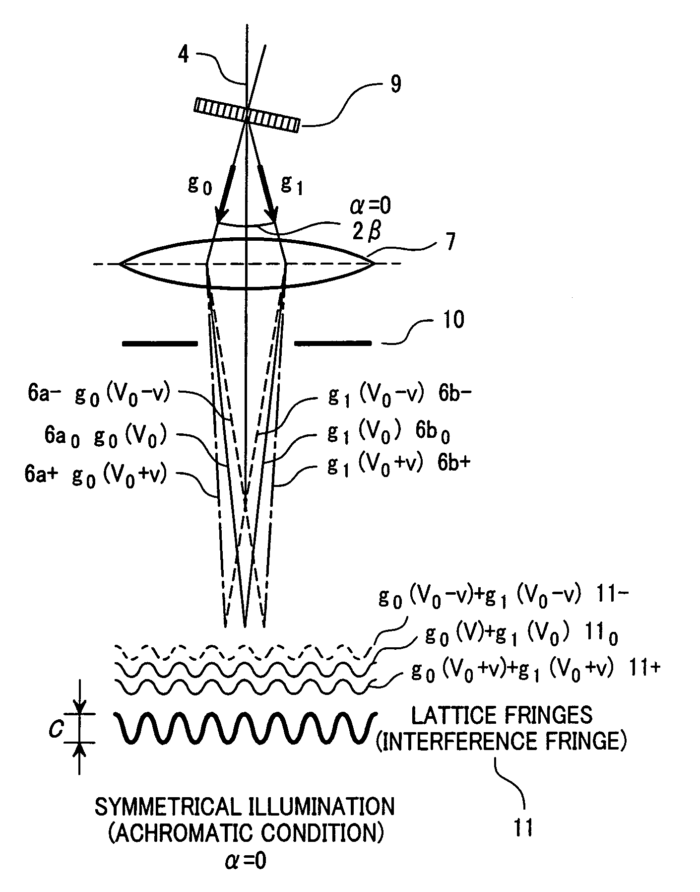
[0059]FIG. 6 illustratively shows the configuration of a transmission electron microscope needed to implement measurement of an information transfer limit in accordance with the present invention. A transmission electron microscope 17 has an electron beam deflector 12 disposed above a crystal thin film 9 for the purpose of changing an incident angle at which an electron beam 4 emanating from an electron source 30 falls on the crystal thin film. Moreover, the transmission electron microscope includes a specimen tilting system 13 that adjusts the angle of a crystalline specimen itself. The electron beam 4 is scattered by the crystal thin film 9, and falls on an objective lens 7 as a diffracted electron beam 6. An aperture system 10 located below the objective lens 7 selects a diffracted wave. A lattice image is formed on an image plane 8 of the objective lens as a result of interference of the selected diffracted wave with other wave. The lattice image is enlarged by intermediate proj...
PUM
 Abstract
Description
Claims
Application Information
 - R&D
- Intellectual Property
- Life Sciences
- Materials
- Tech Scout
- Unparalleled Data Quality
- Higher Quality Content
- 60% Fewer Hallucinations
Browse by: Latest US Patents, China's latest patents, Technical Efficacy Thesaurus, Application Domain, Technology Topic, Popular Technical Reports.
© 2025 PatSnap. All rights reserved.Legal|Privacy policy|Modern Slavery Act Transparency Statement|Sitemap|About US| Contact US: help@patsnap.com


