Charged-particle exposure apparatus

Active Publication Date: 2008-05-01
IMS NANOFABTION
View PDF8 Cites 41 Cited by
  • Summary
  • Abstract
  • Description
  • Claims
  • Application Information

AI Technical Summary

Benefits of technology

[0012]In one advantageous development of the invention, the central aperture is adapted to laterally delimit the patterned beam. This serves to limit the later

Problems solved by technology

Notably, electrodes being under high voltage and providing high electrostatic field strength

Method used


Image

  • Charged-particle exposure apparatus
  • Charged-particle exposure apparatus
  • Charged-particle exposure apparatus

Examples


Embodiment Construction

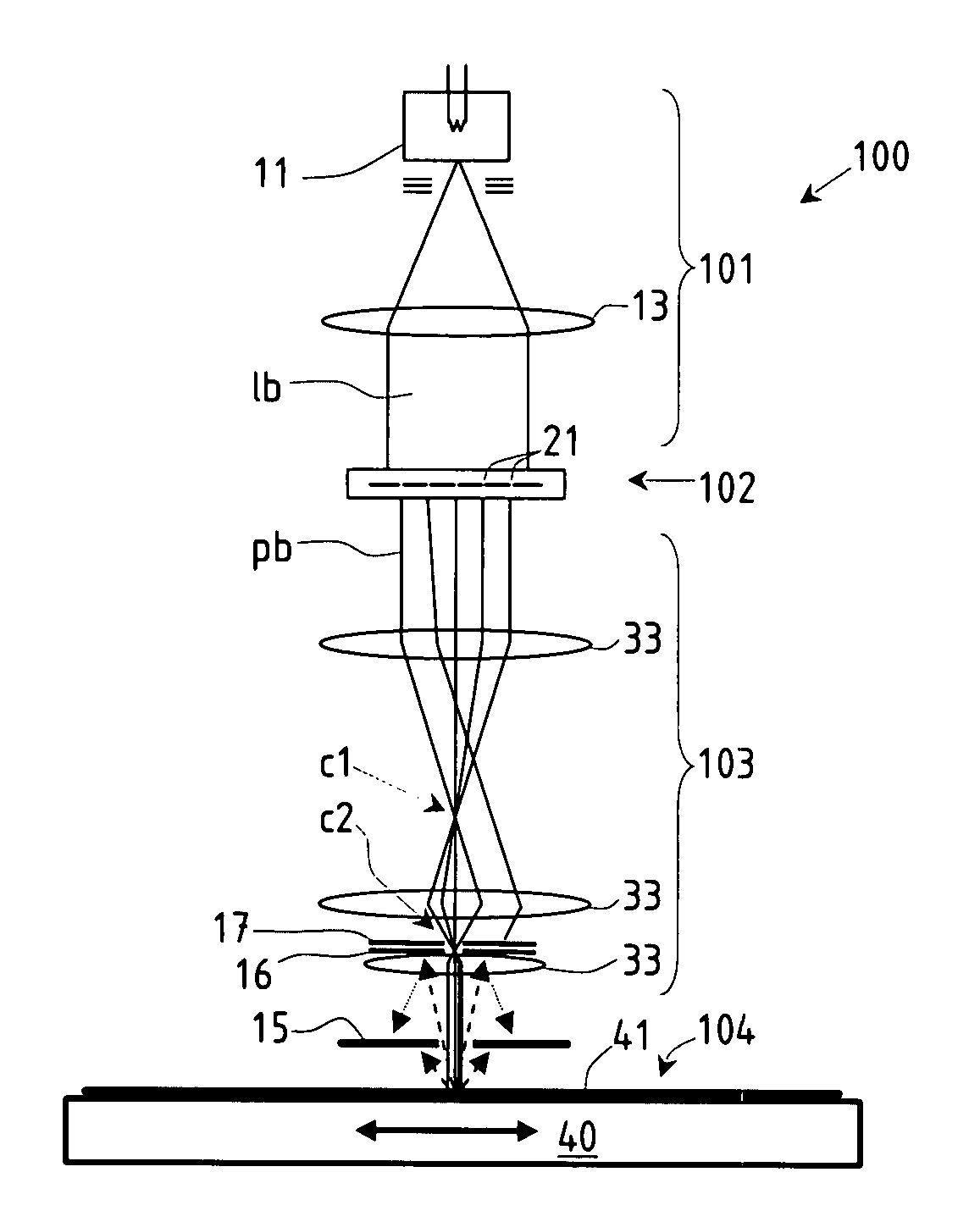
[0035]The preferred embodiment of the invention discussed in the following is based on the PML2-type particle-beam exposure apparatus with a pattern definition (PD) system as disclosed in the U.S. Pat. No. 6,768,125 (=GB 2 389 454 A) of the applicant (assignee), and with a large-reduction projecting system. In the following, first the technical background of the apparatus is discussed as far as relevant to the invention, then embodiments of the invention are discussed in detail. It should be appreciated that the invention is not restricted to the following embodiments nor the PD system, which merely represent one of the possible implementations of the invention; rather, the invention is suitable for other types of processing systems that employ a particle-beam with projection stages as well.

PML2 System

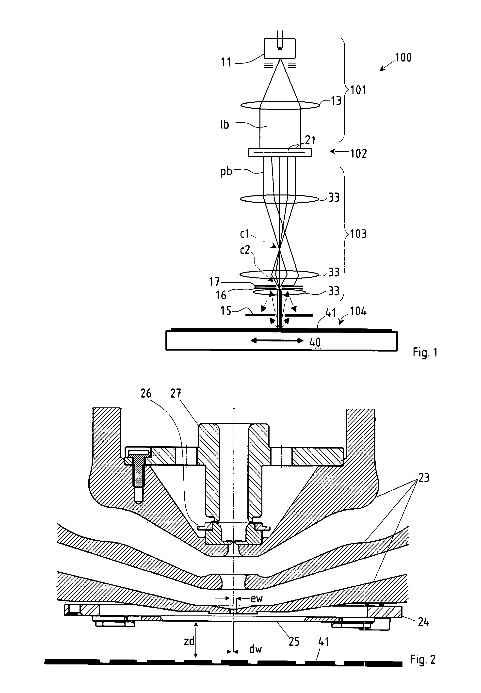
[0036]A schematic overview of a maskless particle-beam exposure apparatus PML2 employing the invention is shown in FIG. 1. In the following, only those details are given as needed to d...


PUM


Abstract

In a particle-beam projection processing apparatus a target (41) is irradiated by means of a beam (pb) of energetic electrically charged particles, using a projection system (103) to image a pattern presented in a pattern definition means (102) onto the target (41) held at position by means of a target stage; no elements—other than the target itself—obstruct the path of the beam after the optical elements of the projection system. In order to reduce contaminations from the target space into the projection system, a protective diaphragm (15) is provided between the projection system and the target stage, having a central aperture surrounding the path of the patterned beam, wherein at least the portions of the diaphragm defining the central aperture are located within a field-free space after the projection system (103).

Description

FIELD OF THE INVENTION AND DESCRIPTION OF PRIOR ART[0001]The invention relates to improvements on particle-beam projection processing apparatus for irradiating a target by means of a beam of energetic electrically charged particles, comprising an illumination system, a pattern definition (PD) means and a projection system in order to project the beam patterned by the PD means onto a target positioned after the projection system. The illumination system serves to generate and form the energetic particles into a wide-area illuminating beam which, preferably, is substantially tele / homocentric at the location of the PD means and whose diameter is greater by at least one order of magnitude than the length of the tele / homocentricity region of the illuminating beam; the PD means, located after the illumination system as seen along the direction of the beam (i.e., downstream), positions an aperture pattern composed of apertures transparent to the energetic particles in the path of the illum...

Claims


Application Information

Patent Timeline
IPC IPC(8): G21K5/04
CPCB82Y10/00B82Y40/00H01J37/02H01J37/045H01J37/09H01J37/3007H01J2237/0835H01J2237/022H01J2237/0435H01J2237/0451H01J2237/0453H01J2237/0458H01J37/3174H01J37/3177
Inventor PLATZGUMMER, ELMAR
Owner IMS NANOFABTION
Why Eureka
Try Eureka