Liquid jet apparatus and printing apparatus

a liquid jet and printing technology, applied in printing, other printing apparatus, etc., can solve the problems of low efficiency of linear driving itself in a transistor, increase of circuit size, increase of cooling radiator plate size, etc., to prevent cost, reduce and prevent the change of the voltage value of the drive signal, effect of preventing the increase of the number of parts

Inactive Publication Date: 2008-05-01
SEIKO EPSON CORP
View PDF11 Cites 46 Cited by
  • Summary
  • Abstract
  • Description
  • Claims
  • Application Information

AI Technical Summary

Benefits of technology

[0010] An object of the invention is to provide a liquid jet apparatus and printing apparatus capable of reducing and preventing the change of vol...

Problems solved by technology

In the current amplifier with such a configuration, however, the linear driving itself in a transistor is low efficiency and it is necessary to use a large scale transistor as the countermeasure of heat generation from the transistor itself.
This leads to a disadvantage of the increase of circuit size and especially the increased size of the cooling radiator plate becomes a major obstacle in terms of layout.
In the method of fee...

Method used


Image

  • Liquid jet apparatus and printing apparatus
  • Liquid jet apparatus and printing apparatus
  • Liquid jet apparatus and printing apparatus

Examples


first embodiment

[0043] Hereinafter, the invention will be described in reference to drawings.

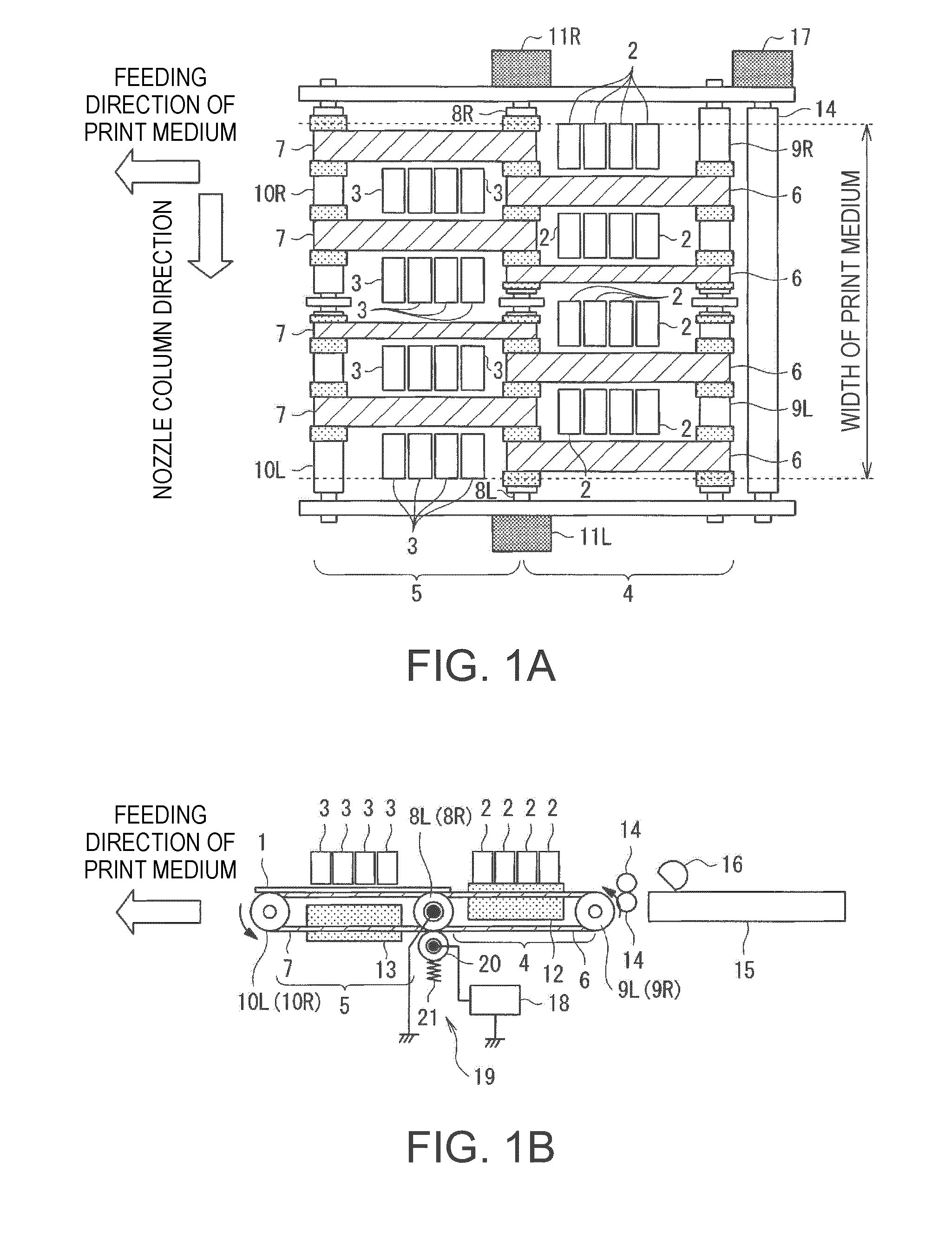
[0044]FIG. 1 is a skeleton framework showing a printing apparatus according to the first embodiment, in which FIG. 1A is a plan view and FIG. 1B is a front view. FIG. 1 indicates a line head printing apparatus, in which a print medium 1 is fed in the direction of arrow in the Figure from right to left in the Figure and printed in a printing area on the way during feeding. Note that a liquid jet head in the first embodiment is arranged at not only one area but also separately into two areas.

[0045] In Figure, a numeral 2 indicates a first liquid jet head provided on the upstream in the direction of feeding of the print medium 1 while a numeral 3 indicates a second liquid jet head provided on the downstream thereof. A first feeding part 4 to feed the print medium 1 is provided under the first liquid jet head 2 while a second feeding part 5 is provided under the second liquid jet head 3. The first feeding part...

third embodiment

[0086] Therefore in the third embodiment, an arithmetic processing shown in FIG. 19 is performed in the arithmetic circuit 28 to calculate a variable power supply voltage VDDACT and to correct the modulation signal by using this variable power supply voltage VDDACT. In this arithmetic processing, the drive pulse selecting data SI&SP and the latch signal LAT are read in step S1 first.

[0087] Next there proceeds to step S2 to calculate the number of the actuators to be driven according to the drive pulse selecting data SI&SP and the latch signal LAT read in step S1.

[0088] Next there proceeds to step S3 to calculate the variable power supply voltage VDDACT according to the number of the actuators to be driven calculated in step S2.

[0089] Next there proceeds to step S4 to return to a main program after outputting the gain according to the variable power supply voltage VDDACT calculated in step S3, to the multiplier 27. It should be noted that the method of setting the gain is the same ...


PUM


Abstract

This invention provides a liquid jet apparatus including: a plurality of nozzles provided at a liquid jet head; an actuator provided corresponding to the nozzles; a driving part that applies a drive signal to the actuator, wherein the driving part includes: a drive waveform signal generating circuit that generates a drive waveform signal to be a reference of a signal controlling the driving of actuator; a modulation circuit that performs a pulse modulation of the drive waveform signal generated in the drive waveform signal generating circuit; a digital power amplifier that performs a power amplification of the modulation signal having been subject to the pulse modulation in the modulation circuit; a smoothing filter that smoothes a power amplification modulation signal having been subject to the power amplification in the digital power amplifier and supplies to the actuator as the drive signal; and a modulation signal correcting part that corrects the modulation signal in accordance with power supply voltage to the digital power amplifier.

Description

BACKGROUND [0001] 1. Technical Field [0002] The present invention relates to a printing device to print predetermined letter or image by producing a jet of minute liquid from a plurality of nozzles to form the particulate (dot) thereof on a print medium. [0003] 2. Related Art [0004] With an ink-jet printer as one of such printing apparatuses, a color print can be easily obtained in general at a low price and with high quality. Accordingly, there has been widely spread to not only offices but also general users, following the popularization of personal computer, digital camera and so on. [0005] Further in the recent ink-jet printer, the printing with high tone is required. Tone is the state of the density of each color included in the pixel indicated by liquid dot. The size of liquid dot corresponding to the density of each color is called gradient and the number of gradients that can be expressed by the liquid dot is called tone number. High tone means a large tone number. So as to ...

Claims


Application Information

Patent Timeline
IPC IPC(8): B41J29/38
CPCB41J2/04541B41J2/04588B41J2/04581B41J2/04593B41J2/04596
Inventor OSHIMA, ATSUSHITABATA, KUNIO
Owner SEIKO EPSON CORP
Why Eureka
Try Eureka