Switching element overcurrent protection circuit which operates within a high-voltage system that incorporates the switching element

a protection circuit and switching element technology, applied in the direction of electronic switching, pulse technique, electrical apparatus, etc., can solve the problems of large overall circuit scale, and further delay in calculating the compensated threshold value by the microcomputer, and achieve accurate circuit configuration and simple circuit configuration

Active Publication Date: 2008-05-01
DENSO CORP
View PDF4 Cites 38 Cited by
  • Summary
  • Abstract
  • Description
  • Claims
  • Application Information

AI Technical Summary

Benefits of technology

[0010]It is an objective of the present invention to overcome the above problems, by providing an overcurrent detection circuit whereby a judgement can be accurately made as to whether excessive current is flowing between the terminals of a switching element, with the overcurrent detection circuit having a simple circuit configuration, and which is applicable to switching elements that are incorporated in circuits which operate at a high voltage, while eliminating a need to utilize electrical isolation devices such as photo-couplers for signal transfer between a high-voltage system and a low-voltage system.
[0018]In either case, the effect is to compensate the comparison operation (for judging whether the switched current being passed by the switching element exceeds a predetermined threshold value) against the temperature dependency of the condition detection signal. Hence, the judgement circuit can obtain a result that is independent of the temperature of the switching element.
[0026]Thus, if the condition detection signal level increases with increasing temperature of the switching element, the analog circuit output signal can be utilized as the threshold voltage in the judgement circuit, to be compared with the condition detection signal. The effects of the temperature dependency of the condition detection signal can thereby be eliminated.
[0027]With such an inverter circuit, the slope of the temperature variation characteristic of the analog circuit output signal can be adjusted as required, by adjusting the ratio of values of the first and second resistors. Hence, the temperature variation characteristic of the output signal produced from the analog circuit can be made substantially similar to the temperature variation characteristic of the condition detection signal. In addition, by adjusting a potential applied to the non-inverting input terminal of the operational amplifier (e.g., a potential produced from a resistive voltage divider) an amount of DC offset of the analog circuit output signal can readily be set as required.
[0028]In that way, the analog circuit output signal can be made appropriate for use as a threshold value which will vary with temperature in the same manner as the condition detection signal. Hence, the operation of the judgement circuit will be unaffected by variations in the temperature of the switching element, since the temperature dependency of the condition detection signal is cancelled by the (ideally) identical temperature dependency of the analog circuit output signal.

Problems solved by technology

However such a configuration presents various problems.
There is a delay in converting the thermistor output into digital data, and a further delay in calculating the compensated threshold value by the microcomputer.
In addition, due to the need to use an A / D converter and a microcomputer, the overall circuit scale is large and complex.
The above problems are not limited to the case of an overcurrent detection circuit, but arise in general when it is necessary to detect a condition of excessive current flow between the terminals of a switching element within a high-voltage system.

Method used


Image

  • Switching element overcurrent protection circuit which operates within a high-voltage system that incorporates the switching element
  • Switching element overcurrent protection circuit which operates within a high-voltage system that incorporates the switching element
  • Switching element overcurrent protection circuit which operates within a high-voltage system that incorporates the switching element

Examples


second embodiment

[0093]A second embodiment of an overcurrent detection circuit will be described in the following referring to the circuit diagram of FIG. 5, with the description being centered on the points of difference from the first embodiment. In FIG. 5, components corresponding to components in the first embodiment are designated by corresponding reference numerals to those of the first embodiment.

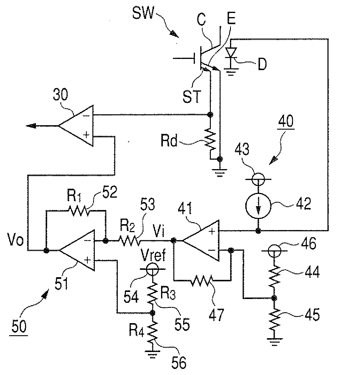
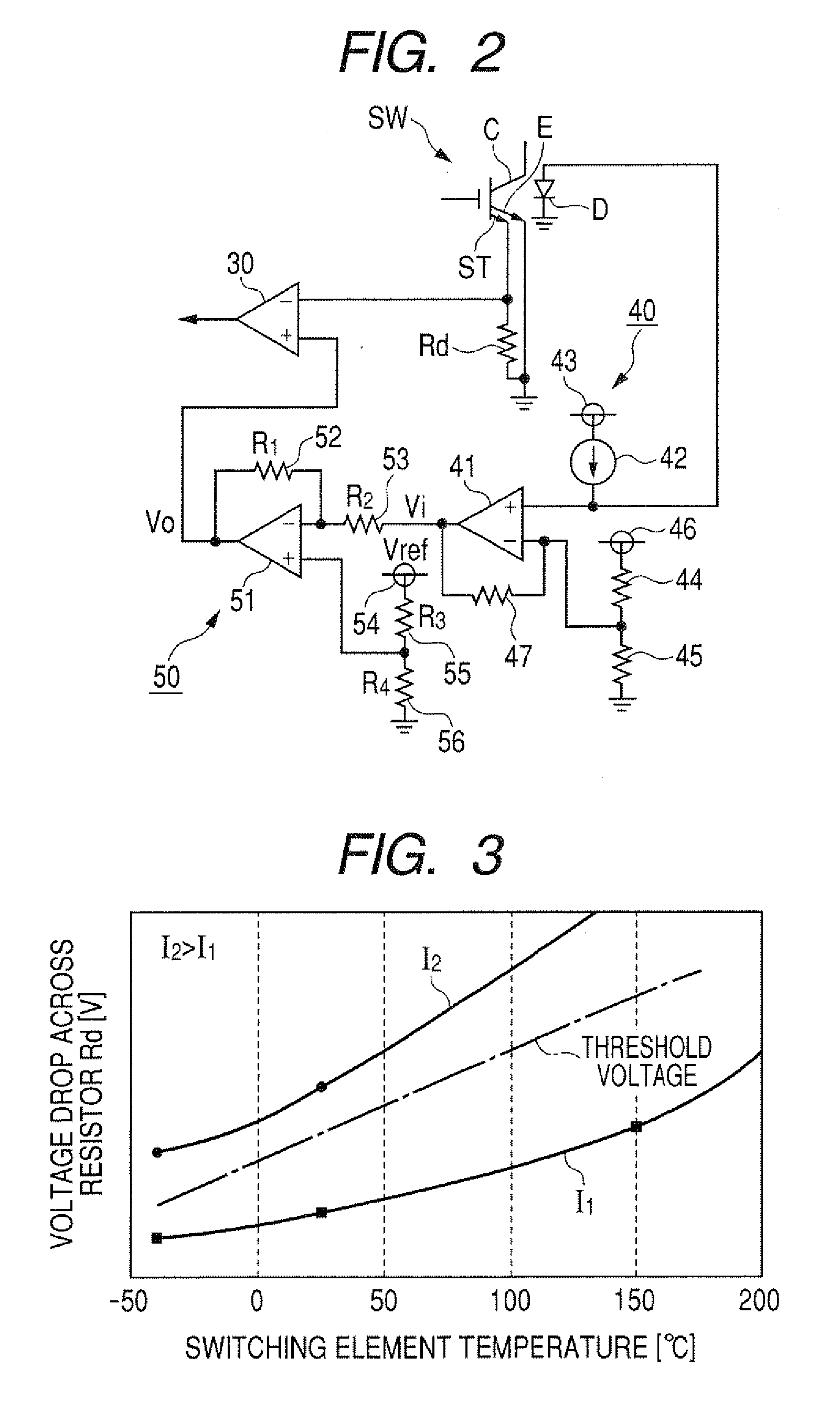
[0094]This embodiment incorporates an output conversion circuit 60, which performs conversion of the temperature detection signal Vi in place of the output conversion circuit 50 of the first embodiment. With the first embodiment, the output conversion circuit 50 converts an approximately linear temperature variation characteristic of a diode to a corresponding approximately linear temperature variation characteristic having an inverted slope direction (e.g., as shown for the threshold voltage in FIG. 3), with the slope and DC voltage offset amount of that characteristic being adjusted appropriately. ...

third embodiment

[0110]A third embodiment of will be described in the following referring to the circuit diagram of FIG. 6, with the description being centered on the points of difference from the first embodiment. In FIG. 6, components corresponding to components shown in FIG. 1 are designated by corresponding reference numerals to those of FIG. 1.

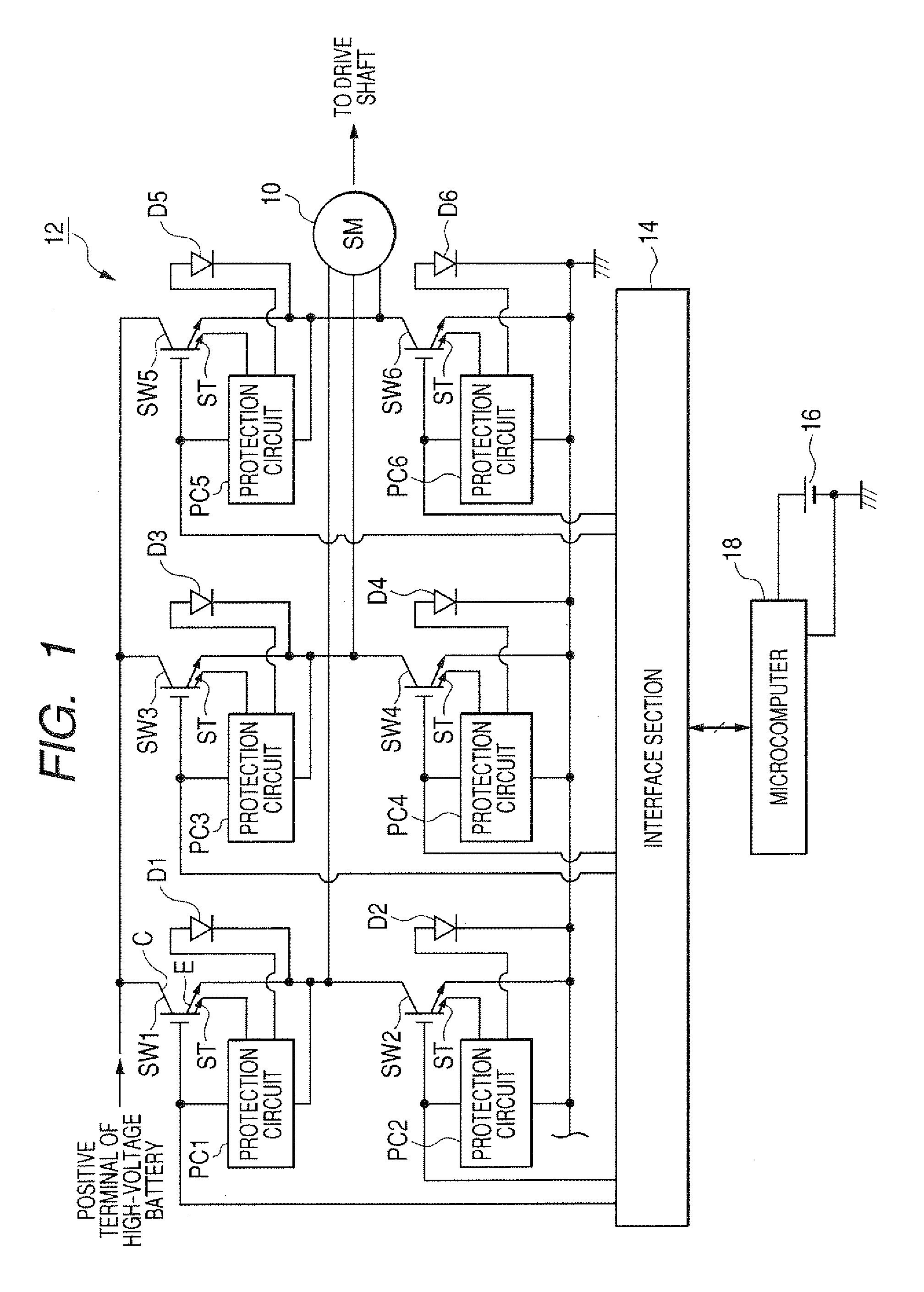
[0111]With this embodiment as shown in FIG. 6, in each upper stage and each lower stage of each phase leg of the inverter 12, a pair of switching elements are connected in parallel. For example the switching elements SW1a, SW1b are connected in parallel in the upper stage of the U-phase leg, while the switching elements SW2a, SW2b are connected in parallel in the lower stage of that phase leg. This is done in order to enable the level of current that flows in each phase of the inverter 12 to be increased, while ensuring that the current that flows in each switching element is maintained within design specifications. With such a configuration, the switchin...

fourth embodiment

[0120]A fourth embodiment will be described in the following referring to the circuit diagram of FIG. 8, which shows an overcurrent detection circuit that is representative of each of respective overcurrent detection circuits incorporated in the protection circuits PC1 to PC6 of this embodiment, with the description being centered on the points of difference from the third embodiment described above. In FIG. 8S, components corresponding to components shown in FIG. 7 are designated by corresponding reference numerals to those of FIG. 7.

[0121]With this embodiment, the respective temperature detection signals Vi(a), Vi(b) outputted from the gain adjustment amplifiers 40a, 40b are applied through resistors 72a, 72b which are of identical value, to the inverting input terminal of the operational amplifier 51. As a results, an averaging circuit is constituted by the combination of the resistors 72a, 72b and the operational amplifier 51, whereby the output conversion circuit 50 sets the le...


PUM


Abstract

A circuit for detecting excessive current flow through a switching element derives an electrical quantity relating to a condition of the switching element and correlated with the current level, and compares the magnitude of that electrical condition quantity with a threshold value corresponding to the maximum allowable level of current. A temperature detection signal indicative of the switching element temperature is converted to a compensation signal having a temperature characteristic which is modified from that of the temperature detection signal, and which is utilized to compensate the magnitude comparison operation against inaccuracy caused by a temperature dependency of the electrical condition quantity.

Description

CROSS-REFERENCE TO RELATED APPLICATIONS[0001]This application is based on and incorporates herein by reference Japanese Patent Application No. 2007-077247 filed on Mar. 23, 2007 and Japanese Patent Application No. 2006-289410 filed on Oct. 25, 2006.BACKGROUND OF THE INVENTION[0002]1. Field of Application[0003]The present invention relates to an overcurrent detection circuit for judging whether an excessive level of current is flowing between the input and output terminals of a switching element.[0004]2. Description of Related Art[0005]An example of such an overcurrent detection circuit is described in Japanese Patent No. 3367699, referred to in the following as reference document 1. With the overcurrent detection circuit of reference document 1, judgement of the level of current flowing between the collector and emitter of an IGBT (insulated gate bipolar transistor) is made based on a correlation between the collector-emitter voltage and the level of current. That is to say, the col...

Claims


Application Information

Patent Timeline
Patent Type & Authority Applications(United States)
IPC IPC(8): H02H7/12H02H5/04
CPCH03K17/0828H03K2017/0806H03K17/14H03K2217/0027
Inventor MAEBARA, TSUNEOINOSHITA, RYOUSUKEOOHAMA, KENICHIISHIURA, DAISUKE
Owner DENSO CORP
Why Eureka
Try Eureka