Imaging arrangement and system for imaging

a computed tomography and imaging arrangement technology, applied in the field of cone beam computed tomography scanning, can solve the problems of slow reading out, tft-panels have a number of limitations when it comes to cone beam ct imaging, and the detection technology cannot be used to implement wide detectors

Active Publication Date: 2008-05-01
XCOUNTER
View PDF24 Cites 14 Cited by
  • Summary
  • Abstract
  • Description
  • Claims
  • Application Information

AI Technical Summary

Benefits of technology

[0019]The imaging arrangement in accordance with the present invention can be read out up to 25 000 times per second or even faster. The resolution is high and the pixel size is small, down to 0.05 mm. The photon counting and gaseous avalanche amplification ensures that there is no noise contributing to the image, besides the statistical fluctuation of the X-ray photon flux. The detector has no lag, ghosting or blooming effects. Further, the performance of the imaging arrangement is not degraded by scattered ...

Problems solved by technology

This detector technology cannot be used for implementing wide detectors due to the high costs and problems to read out the signals from a wider detector.
However, the TFT-panels have a number of limitations when it comes to cone beam CT imaging.
Firstly, they are slow to read out and can at most be read out 60 times per second, but then with rather large pixel size.
This is far too slow for CT applications when one wishes to read out the detector one thousand times per revolution or more.
Secondly, the TFT-panels have too high electronic noise, which adds up when thousands of images are combined to form the CT slice images or 3D volumes.
Thirdly, area detectors are sensitive to X-rays that scatter in the patient and hit the detect...

Method used


Image

  • Imaging arrangement and system for imaging
  • Imaging arrangement and system for imaging
  • Imaging arrangement and system for imaging

Examples


Embodiment Construction

[0029]In the following the present invention is described and exemplified by means of a particular medical application, namely mammography. The invention is however applicable in other areas as well, with suitable modifications.

[0030]Mammography is an example of an important application of medical imaging. In a mammography procedure of today the breast of the patient is compressed between two compression plates and the X-ray source is activated and the X-ray detector captures a 2D image of the breast. The compression of the breast is most uncomfortable to the patient. Further, it is important that the image quality is high, since breast cancer can, for example, be missed by being obscured by radiographically dense, fibrograndular breast tissue. There are thus a number of drawbacks related to the field of mammography. These drawbacks, among others, are overcome by means of the present invention.

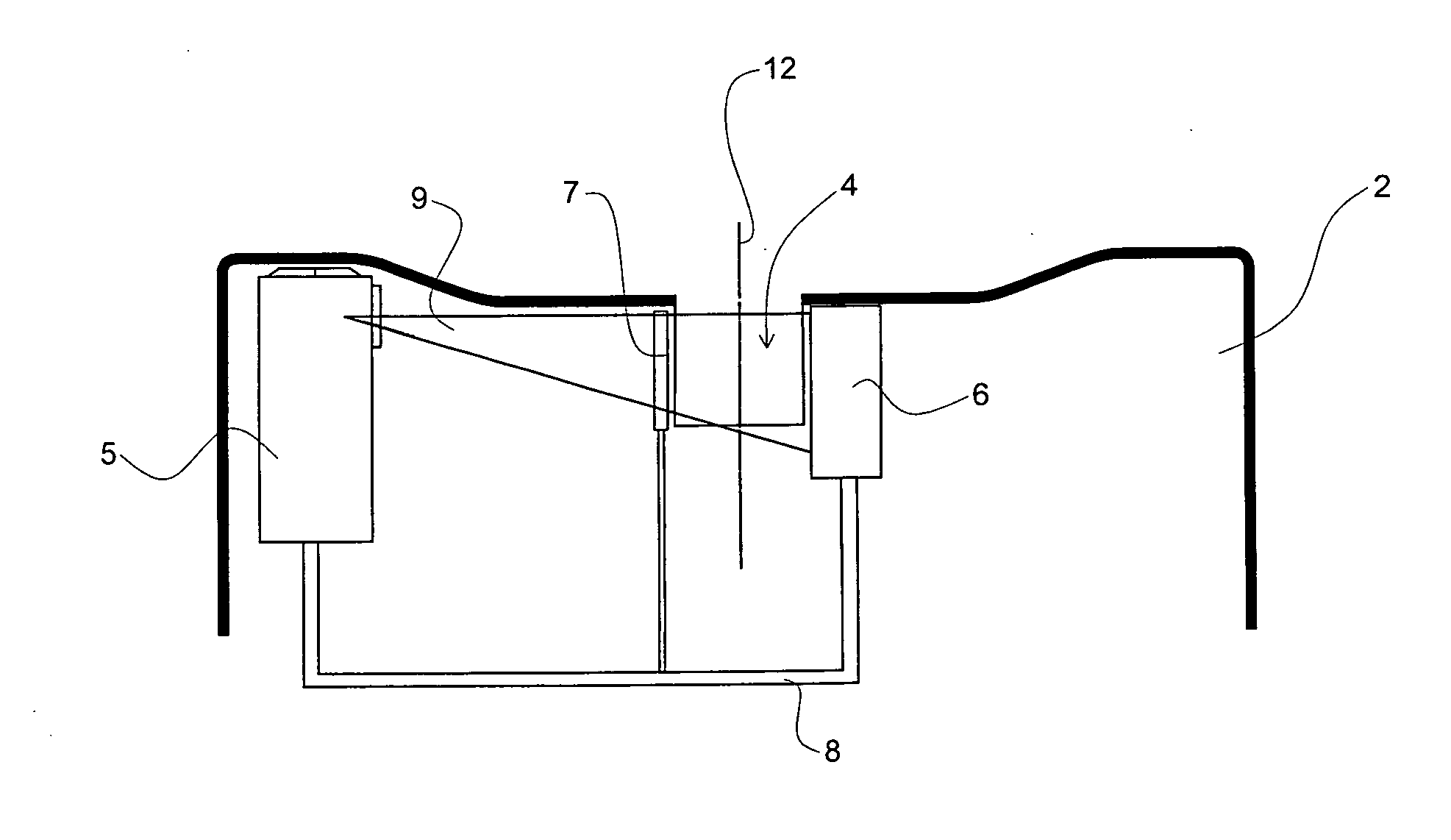
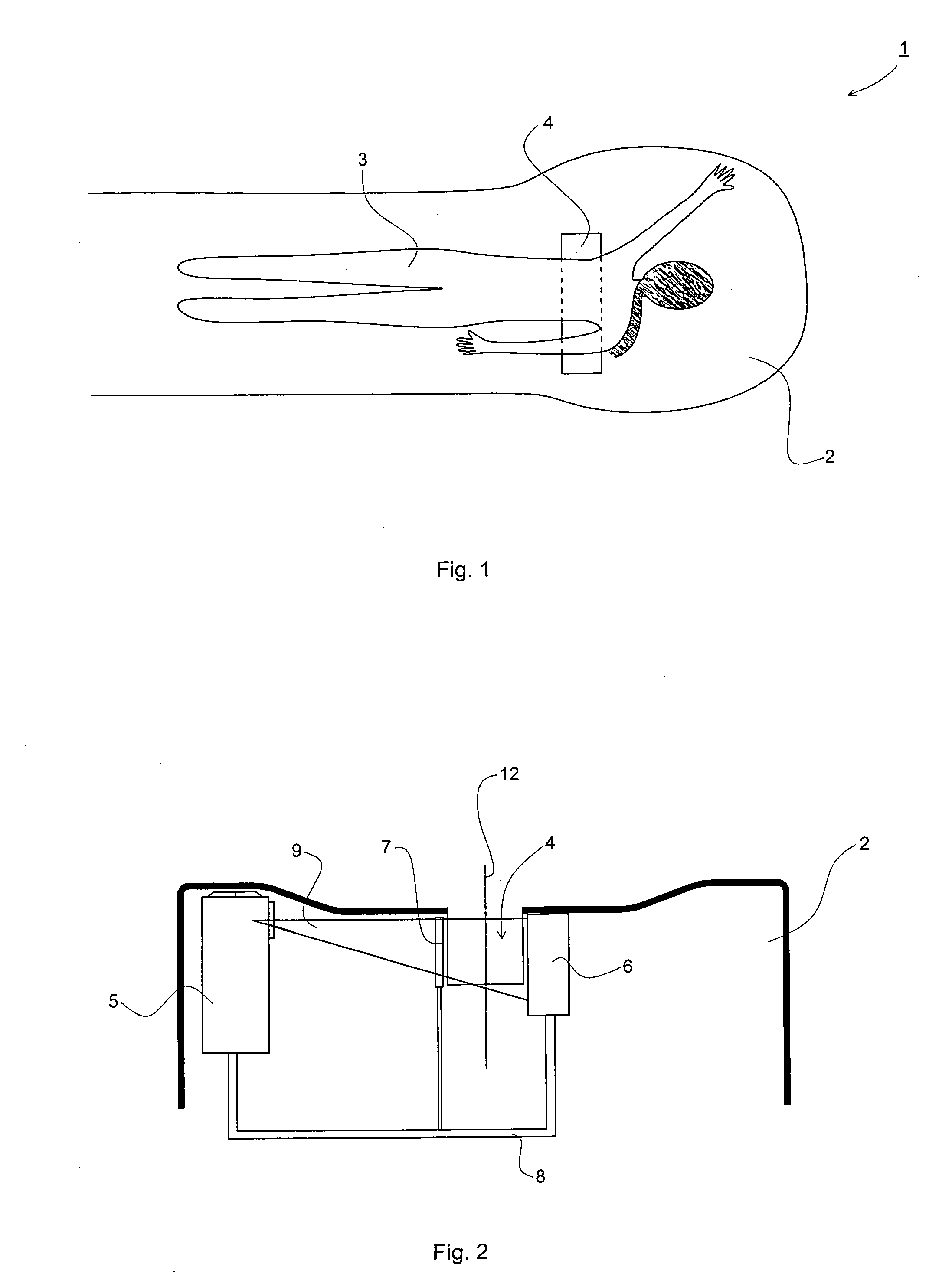
[0031]FIG. 1 illustrates schematically the present invention in a mammography application....


PUM


Abstract

The invention relates to an imaging arrangement for imaging an object. The imaging arrangement comprises: an X-ray source 5; an X-ray detector 6 arranged to receive X-rays transmitted through the object from the X-ray source 5, wherein the X-ray detector 6 comprises a gaseous-based edge-on direction sensitive line detector provided with an electron avalanche amplifier, and wherein the line detector is adapted to record a line image of radiation as transmitted through the object; and a support device 8 to which the X-ray source 5 and the X-ray detector 6 are attached so as to be arranged on opposite sides of the object, and wherein the support device 8 is arranged to rotate around the object and is also arranged to be movable in relation to the object. The invention also relates to a system comprising such imaging arrangement.

Description

PRIORITY STATEMENT[0001]This application claims benefit of priority under 35 U.S.C. §119 from Swedish Patent Application No. 0602292-5 filed on Oct. 31, 2006, in the Swedish Patent Office, the disclosure of which is incorporated herein by reference in its entirety.FIELD OF THE INVENTION[0002]The present invention relates to the field of cone beam computed tomography scanning, and in particular to an imaging arrangement and a system for imaging by means of such cone beam computed tomography.BACKGROUND OF THE INVENTION[0003]Computed Tomography Scanning (CT scanning), also denoted computerized tomography or computed axial tomography (CAT), is a medical imaging method employing imaging by sectioning or 3D reconstruction. In the CT-scanning an X-ray source and an X-ray detector are arranged opposite one another on an arrangement that rotates around a patient. The X-ray source transmits radiation through the patient and the X-ray detector measures the attenuated radiation. The radiation i...

Claims


Application Information

Patent Timeline
IPC IPC(8): H05G1/60A61B6/00G01N23/00G21K1/12
CPCA61B6/032A61B6/0435A61B6/4014A61B6/4035A61B6/4085A61B6/5247A61B6/502A61B8/0825A61B8/4416A61B6/027A61B6/4417A61B6/482A61N5/10G01N23/083
Inventor ULLBERG, CHRISTERFRANCKE, TOM
Owner XCOUNTER
Why Eureka
Try Eureka