Percutaneous spinal stenosis treatment

a spinal stenosis and percutaneous technology, applied in the field of medical/surgical devices and methods, can solve the problems of developing less invasive surgical methods and devices, posing many challenges, and often compounding the challenges

Inactive Publication Date: 2008-05-01
BAXANO
View PDF99 Cites 181 Cited by
  • Summary
  • Abstract
  • Description
  • Claims
  • Application Information

AI Technical Summary

Benefits of technology

[0033] The system may optionally further include a suction device for removing the cut ligamentum flavum tissue through the lumen. The system may optionally include an irrigation device for passing fluid through the lumen. The system may further include a substance disposed in the lumen of the tissue removal device for delivery through the aperture, wherein the substance is selected from the group consisting of a hemostatic agent, an analgesic, an anesthetic and a steroid.
[0034] The system may further include one or more nerve stimulation members, such as those describe

Problems solved by technology

Developing less invasive surgical methods and devices, however, poses many challenges.
These challenges are often compounded when target tissues of a given procedure reside very close to one or more vital, non-target tissues.
Spinal stenosis occurs when nerve tissue and/or the blood vessels supplying nerve tissue in the spine become impinged by one or more structures the lower (or lumbar) spine and can cause severe pain, numbness and/or loss of function in the lower back and/or one or both lower limb.
Impingement of neural and/or neurovascular tissue in the spine by one or more of these tissues may cause pain, numbness and/or loss of strength or mobility in one or both of a patient's lower limbs and/or of the patient's back.
When these conservative treatment options fail and symptoms are severe, as is frequently the case, surgery may be required to remove impinging tissue and decompress the impinged nerve tissue.
Removal of vertebral bone, as occurs in laminectomy and facetectomy, often leaves the effected area of the spine very unstable, leading to a need for an additional highly invasive fusio

Method used


Image

  • Percutaneous spinal stenosis treatment
  • Percutaneous spinal stenosis treatment
  • Percutaneous spinal stenosis treatment

Examples


Embodiment Construction

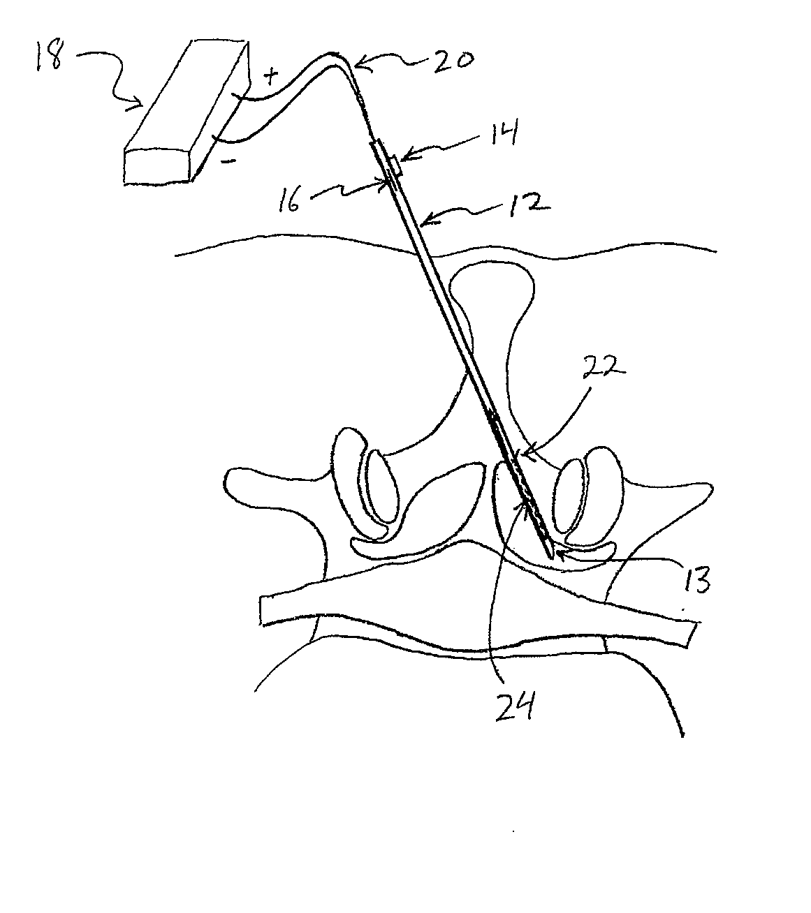
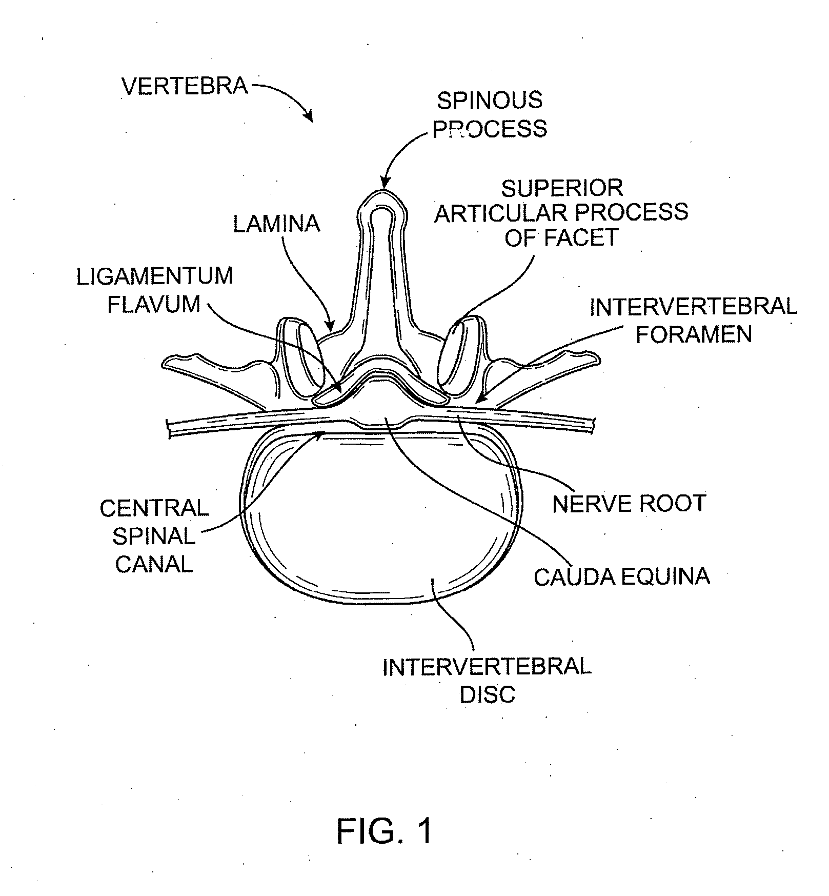
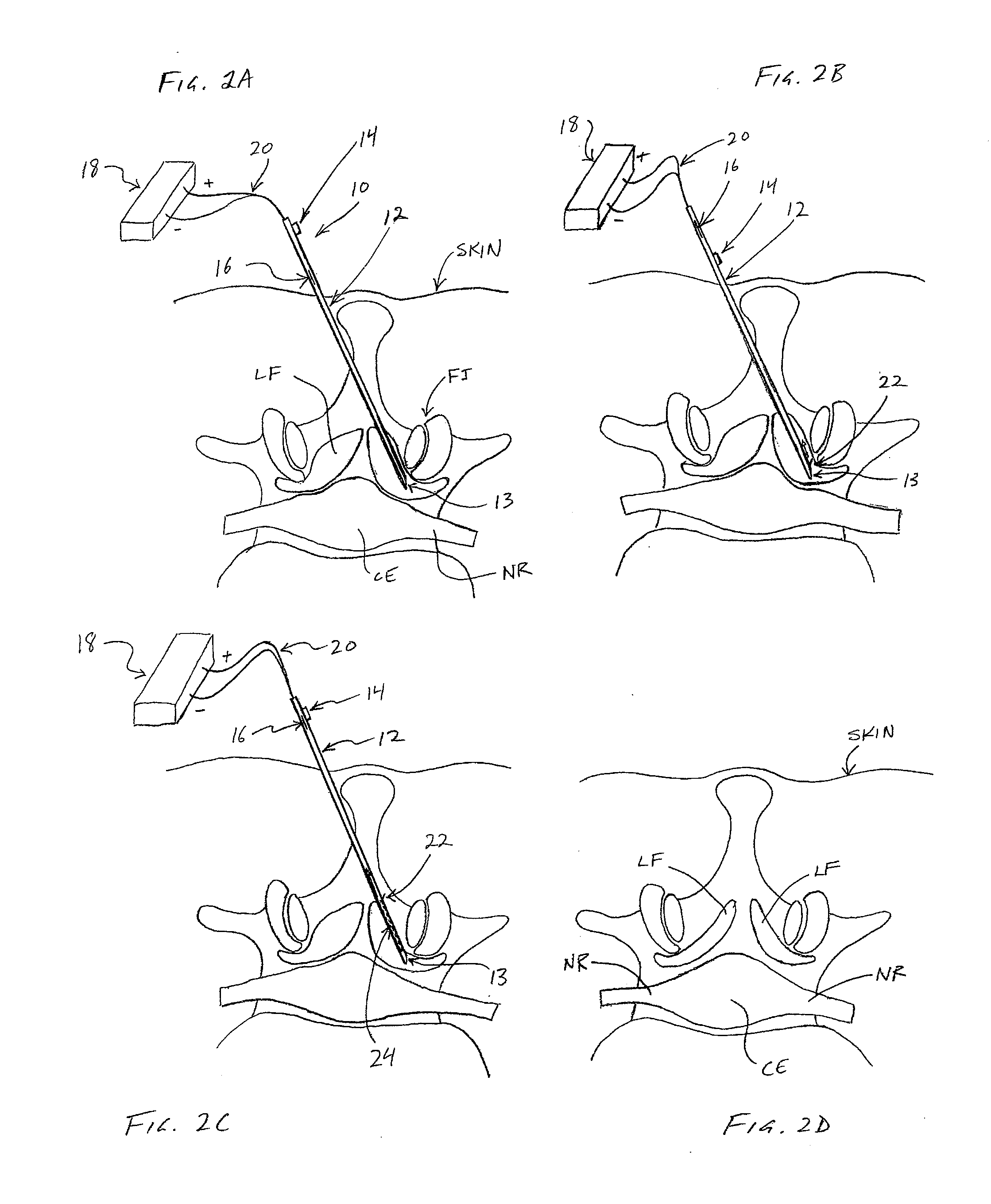
[0065] Referring to FIGS. 2A-2D, one embodiment of a method for removing ligamentum flavum (LF) tissue from a patient's spine is demonstrated. In FIGS. 2A-2D, a partial top view of a vertebra is shown, including ligamentum flavum (LF), facet joint (FJ), nerve root (NR) and cauda equina (CE). The patient's skin is also shown, although none of the anatomical structures, nor the various devices used therein, are necessarily drawn to scale.

[0066] In one embodiment, referring to FIG. 2A, a tissue removal device 10 may be advanced percutaneously through a patient's skin to position a distal tip 13 in the ligamentum flavum (LF) tissue. Device 10 may comprise a cannula (or “needle”) and in some embodiments may include an elongate shaft 12 (including distal tip 13), a first actuator 14 for extending a cutting member 22 out of shaft 12, and a second actuator 16 for moving cutting member 22 along shaft 12 to cut tissue. In some embodiments, cutting member 22 may be coupled with an energy sour...


PUM


Abstract

A method for percutaneously removing ligamentum flavum tissue in a spine to treat spinal stenosis may involve percutaneously advancing a distal portion of a tissue removal cannula into the ligamentum flavum tissue, uncovering a side-opening aperture disposed on the distal portion of the cannula to expose a tissue cutter disposed in the cannula, and cutting ligamentum flavum tissue using the tissue cutter while the aperture is uncovered. A device for percutaneously removing ligamentum flavum tissue in a spine to treat spinal stenosis may include a cannula including a side-facing aperture, an aperture cover slidably coupled with the cannula and configured to advance and retract to cover and uncover the aperture, and a tissue cutter slidably disposed within the cannula and configured to extend through the aperture to cut ligamentum flavum tissue.

Description

CROSS REFERENCE TO RELATED APPLICATIONS [0001] This application claims priority to U.S. Provisional Patent Application Ser. No. 60 / 863,544 (Attorney Docket No. 10376-710.101), entitled “Percutaneous Spinal Stenosis Treatment,” and filed Oct. 30, 2006, the full disclosure of which is hereby incorporated by reference.FIELD OF THE INVENTION [0002] The present invention relates generally to medical / surgical devices and methods. More specifically, the present invention relates to devices and methods for spinal stenosis treatment. BACKGROUND OF THE INVENTION [0003] In recent years, less invasive (or “minimally invasive”) surgical techniques have become increasingly more popular, as physicians, patients and medical device innovators have sought to reduce the trauma, recovery time and side effects typically associated with conventional surgery. Developing less invasive surgical methods and devices, however, poses many challenges. For example, less invasive techniques typically involve worki...

Claims


Application Information

Patent Timeline
IPC IPC(8): A61B17/32A61B18/14A61N1/36
CPCA61B5/04001A61B2019/481A61B5/4893A61B10/0275A61B17/221A61B17/320016A61B17/320725A61B17/320758A61B17/320783A61B18/1482A61B2017/00261A61B2017/00336A61B2017/320733A61B2018/0044A61B2018/1472A61B2019/4027A61B5/0488A61B2090/0427A61B2090/08021A61B5/24A61B5/389
Inventor SCHMITZ, GREGORY P.BLEICH, JEFFERY L.MILLER, ERIC C.SMITH, SCOTT M.
Owner BAXANO
Why Eureka
Try Eureka