Machining simulation system

a simulation system and machining technology, applied in the direction of process control, machine control, instruments, etc., can solve the problems of inability to the numerical control apparatus provided on the worksite cannot mutually readjust the differences in the machining simulation conditions, and the separation of simulation contents, so as to reduce the number and frequency of setting errors, simplify the work, and reduce the effect of setting work

Active Publication Date: 2008-05-01
OKUMA CORP
View PDF3 Cites 13 Cited by
  • Summary
  • Abstract
  • Description
  • Claims
  • Application Information

AI Technical Summary

Benefits of technology

[0049] In this manner, the present invention enables the numerical control apparatus of a worksite to use shape model information and setup positional data set by the machining simulation apparatus of a production engineering division. Thus, an operator of the production engineering division is not required to generate a paper document or other medium that describes or indicates the preparatory planning information.
[0050] With the present invention, an operator of the worksite is not required to set all of the data for the numerical control apparatus. Because the setting work for the numerical control apparatus is substantially limited to setting a small amount of correction data reflecting a machining processing environment, the

Problems solved by technology

For example, a worksite environment may prevent preparation of a tool designated by an operator of the production engineering division, or may make it impossible to install the tool at a designated position.
Therefore, the machining simulation apparatus provided in the production engineering division and the numerical control apparatus provided on the worksite are unable to mutually readjust the differences in the machining simulation conditions.
The above-described conventional system cannot readjust the separated simulation contents and simulation conditions.
In other words, the above-described conventional system cannot perform an adjustment between the machining simulation apparatus performing a simulation prior to an actual machining operation and th

Method used


Image

  • Machining simulation system
  • Machining simulation system
  • Machining simulation system

Examples


Embodiment Construction

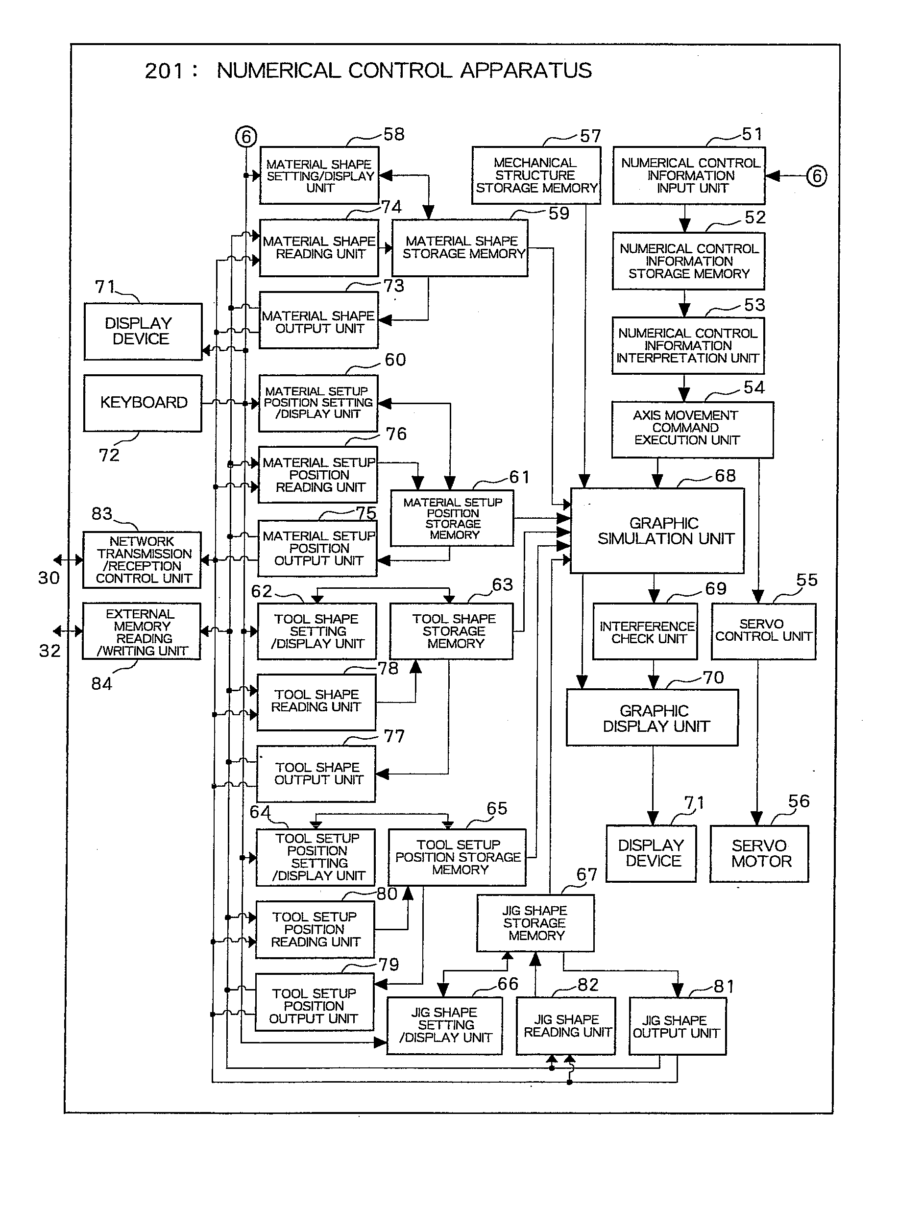
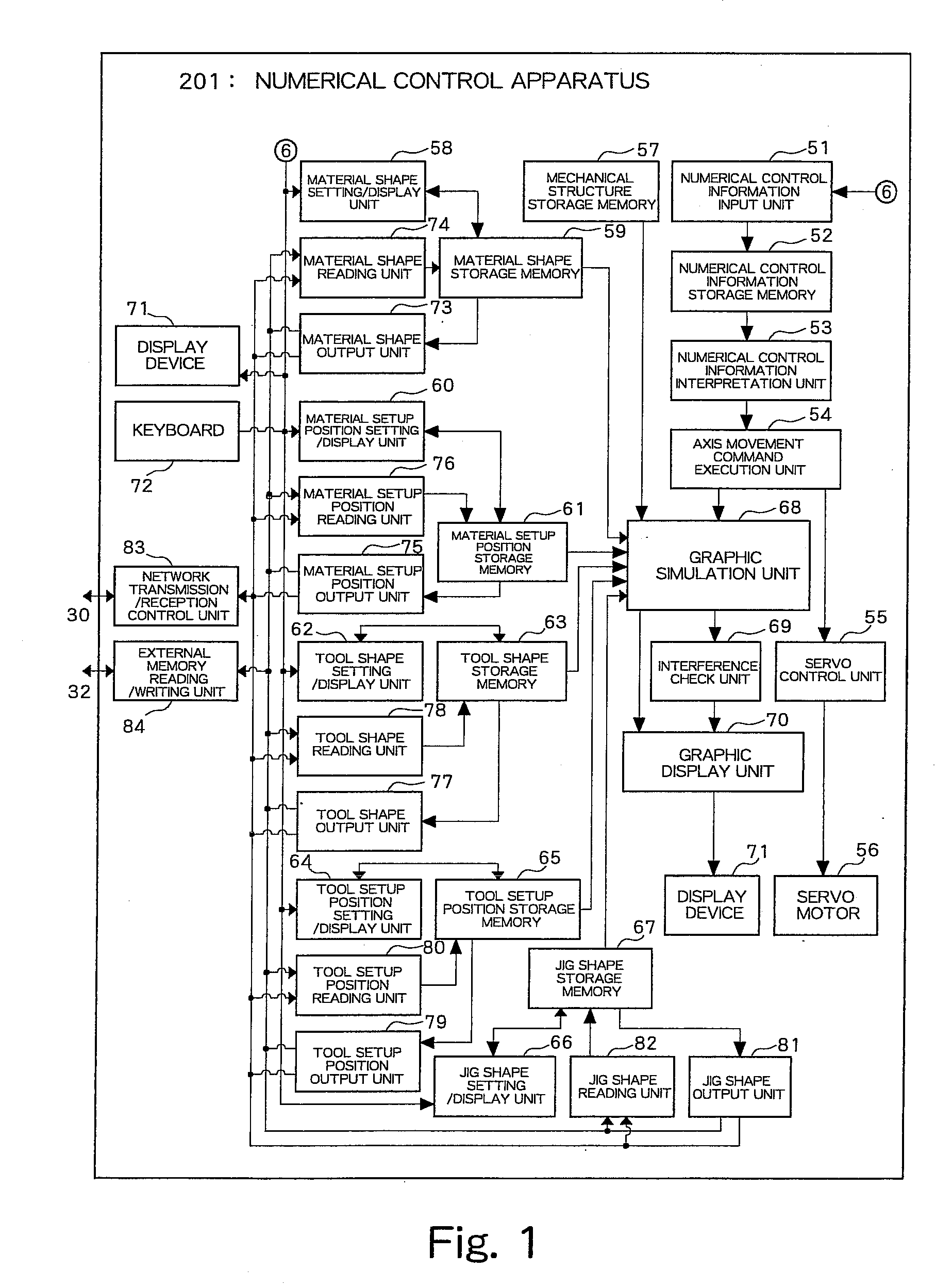
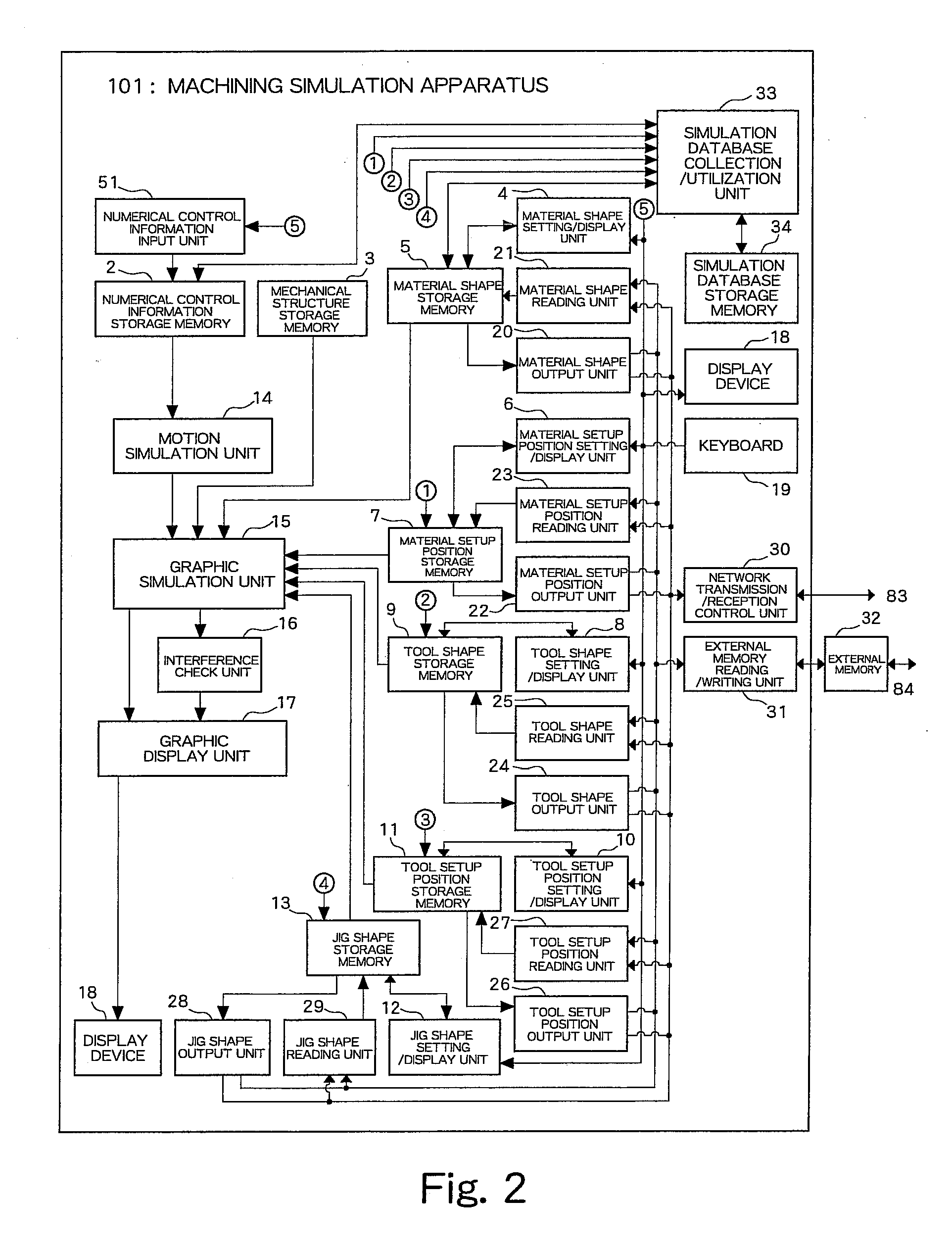
[0065]FIGS. 1 and 2 are block diagrams of an exemplary embodiment of the present invention. In FIGS. 1 and 2, functional components similar to those described in FIGS. 6 and 7 are denoted by the same reference numerals.

[0066] In a machining simulation apparatus 101, a material shape output unit 20 generates a material shape model and outputs the generated model to a network transmission / reception control unit 30 that can transmit the received model to a numerical control apparatus 201 via a network. Furthermore, the material shape output unit 20 can output the generated material shape model to an external memory 32 via an external memory reading / writing unit 31.

[0067] Similarly, a material setup position output unit 22 generates a material setup position and outputs the generated positional information to the network transmission / reception control unit 30 that can transmit the received information to the numerical control apparatus 201 via the network. Furthermore, the material se...


PUM


Abstract

A numerical control apparatus can perform a machining simulation or an interference check that reflects worksite information. However, a machining simulation apparatus cannot use worksite information in a machining simulation or an interference check. Thus, simulation conditions of the machining simulation apparatus are different from those of the numerical control apparatus. To solve this problem, a machining simulation apparatus and a numerical control apparatus according to the present invention can communicate with each other via a communication unit or a storage medium so as to mutually transmit and receive data. The machining simulation apparatus includes a network transmission/reception control unit or an external memory reading/writing unit. Similarly, the numerical control apparatus includes a network transmission/reception control unit or an external memory reading/writing unit.

Description

CROSS-REFERENCE TO RELATED APPLICATIONS [0001] This application claims priority to Japanese Patent Application No. 2006-293961 filed on Oct. 30, 2006, which is incorporated herein by reference in its entirety. BACKGROUND OF THE INVENTION [0002] 1. Field of the Invention [0003] The present invention relates to a machining simulation system including a numerical control apparatus configured to control a machining motion of a machine tool and a machining simulation apparatus configured to perform a simulation prior to an actual machining operation. [0004] 2. Description of the Related Art [0005] A numerical control apparatus can control a machine tool according to numerical control information input by an operator of a production engineering division who can use a machining simulation apparatus. The machining simulation apparatus has a machining simulation function (including an interference check function) for checking an motion of a machine tool to be realized according to a machinin...

Claims


Application Information

Patent Timeline
IPC IPC(8): G06G7/48
CPCG05B2219/35308G05B19/4069
Inventor FUKAYA, YASUSHIKUNIMITSU, KATSUNORI
Owner OKUMA CORP
Why Eureka
Try Eureka