Devices and systems for measurement of position of drilling related equipment

a technology for measuring equipment and drilling related equipment, which is applied in the direction of surveying, drilling pipes, and accessories of wellbore/wells, etc., can solve the problems of increasing the number of joints and conventional depth measurement systems, and the inability to provide the accuracy needed to position wellbore equipment within a narrow zone of interes

Inactive Publication Date: 2008-05-08
BAKER HUGHES INC
View PDF14 Cites 55 Cited by
  • Summary
  • Abstract
  • Description
  • Claims
  • Application Information

AI Technical Summary

Benefits of technology

[0010] In embodiments using an optical signal, an exemplary position acquisition device includes a laser positioned at a selected location on a rig. The laser directs an optical signal, the laser beam, to the target object. A receiver positioned on the rig receives the optical signal reflected from the target object and a processor processes the reflected signal to determ

Problems solved by technology

Often, however, additional joints are continually being added to the string.
Conventional depth measurement systems, however, may not

Method used


Image

  • Devices and systems for measurement of position of drilling related equipment
  • Devices and systems for measurement of position of drilling related equipment
  • Devices and systems for measurement of position of drilling related equipment

Examples


Embodiment Construction

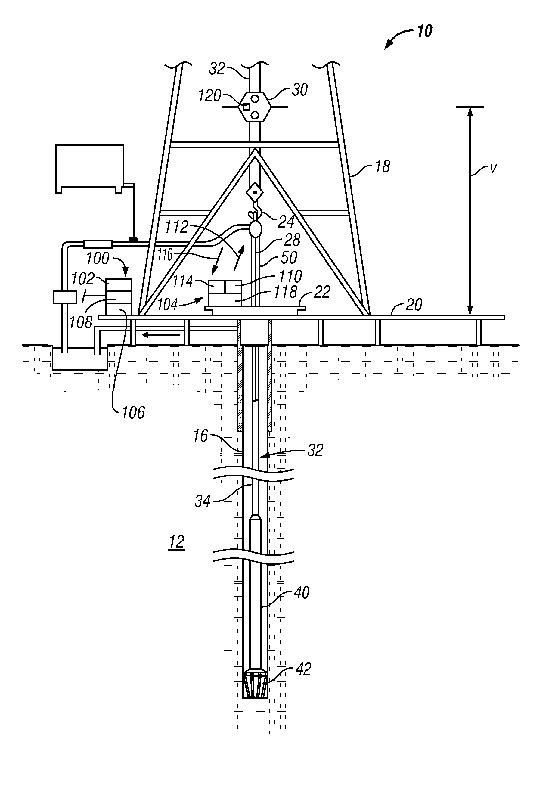
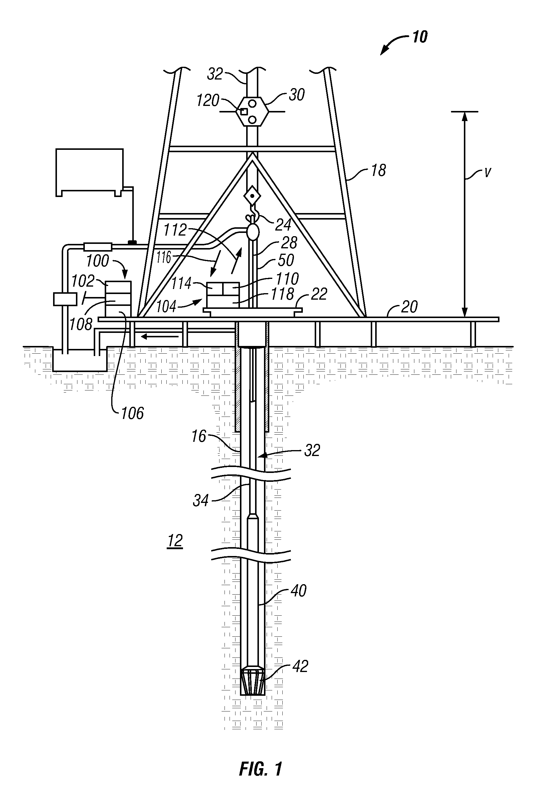
[0015] The present disclosure, in one aspect relates to devices and methods for providing absolute depth information for a tubular string such as a drill string conveyed into a wellbore in a subterranean formation. The present disclosure is susceptible to embodiments of different forms. There are shown in the drawings, and herein will be described in detail, specific embodiments of the present disclosure with the understanding that the present disclosure is to be considered an exemplification of the principles of the disclosure, and is not intended to limit the disclosure to that illustrated and described herein.

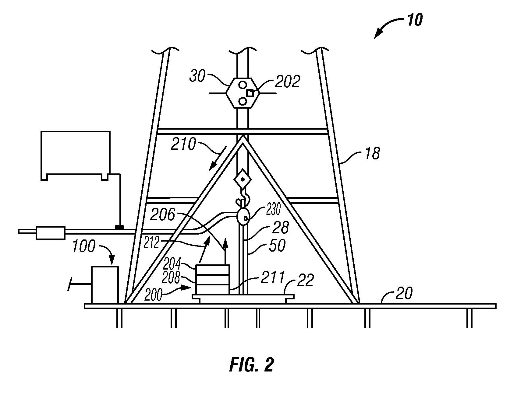
[0016] Referring initially to FIG. 1, there is shown a drill rig 10 positioned over a formation of interest 12. As shown, a wellbore 16 is being drilled into the earth under control of surface equipment including a derrick 18, a derrick or drill floor 20, a hook 24, a kelly joint 28, and a traveling block 30. Other equipment known in the art such as draw works are not shown...


PUM


Abstract

A depth measurement system for determining an absolute depth of a drill string uses a position acquisition device to determine a length value for a joint or stand being added to the drill string. The position acquisition device receives a signal from a target object associated with the added joint. The processed signal can be an optical signal, a radio signal, an acoustic signal, or other suitable signal. Using techniques such as time lapse, Doppler effect or phase shift, the depth measurement system determines a position parameter such as distance or position based on the received signal. Thereafter, the processor determines the absolute depth of the drill string by summing a length of each joint making up the drill string and correcting for the position of the newly added joint.

Description

CROSS-REFERENCE TO RELATED APPLICATIONS [0001] This application takes priority from U.S. Provisional Patent application Ser. No. 60 / 856,686 Nov. 3, 2006.BACKGROUND OF THE DISCLOSURE [0002] 1. Field of the Disclosure [0003] This disclosure relates generally to devices, systems and methods for determining position or location of equipment used in connection with the drilling, completion and / or workover of oilfield wells. [0004] 2. Description of the Related Art [0005] Valuable hydrocarbon deposits, such as those containing oil and gas, are often found in subterranean formations located thousands of feet below the surface of the Earth. To recover these hydrocarbon deposits, boreholes or wellbores are drilled by rotating a drill bit attached to a drilling assembly (also referred to herein as a “bottom hole assembly” or “BHA”). Such a drilling assembly is attached to the downhole end of a tubing or drill string made up of jointed rigid pipe or a flexible tubing coiled on a reel (“coiled ...

Claims


Application Information

Patent Timeline
IPC IPC(8): E21B47/09
CPCE21B47/04E21B44/00E21B19/00
Inventor HAMPTON, DAVIDLOOS, ROB G.ERIKSEN, BERNT
Owner BAKER HUGHES INC
Why Eureka
Try Eureka