Modular landscaper

a module and landscaper technology, applied in the field of modular landscapers, can solve the problems of affecting the use of the device, annoying and damaging the hearing of the user, and the general noise of the motorized yard and driveway device, and achieve the effect of rapid rotation

Inactive Publication Date: 2008-05-08
UMAGINATION LABS
View PDF26 Cites 101 Cited by
  • Summary
  • Abstract
  • Description
  • Claims
  • Application Information

AI Technical Summary

Benefits of technology

[0016] In another aspect of the invention, a wheeled blower may comprise a frame for receiving an operating force from a user of the blower; two oversized wheels, each wheel rotating about an axle secured to the frame, the wheels independently rotating in response to the operating force, causing the system to roll on the wheels along a surface; a radial blade fan for dispersing material away from the blower; and a drive train for transferring torque derived from the rotating wheels to the radial blade fan, causing the fan to rapidly spin, the fan outlet positioned for blowing debris on the surface away from the sweeper.
[0017] In another aspect of the invention, a wheeled rotary mower may comprise a frame for receiving an operating force from a user of the mower; two oversized wheels, each wheel rotating about an axle secured to the frame, the wheels independently rotating in respo

Problems solved by technology

Aside from the trouble and expense of owning, storing, maintaining, and operating all of these devices, they are generally powered by electric motors or other gas or combustion engines that are noisy and pollute the environment and pose certain environmental and personal hazards from the motors, their fuel, and their electric power supplies.
Such motorized yard and driveway devices are also generally noisy, which especially in close suburban or urban settings may annoy family and neighbors as well as annoy and damage the hearing of the user of the devices.
Conventional wheeled reel mowers are well known to generally be limited in practical application to lawns of no more than approxim

Method used


Image

  • Modular landscaper
  • Modular landscaper
  • Modular landscaper

Examples


Embodiment Construction

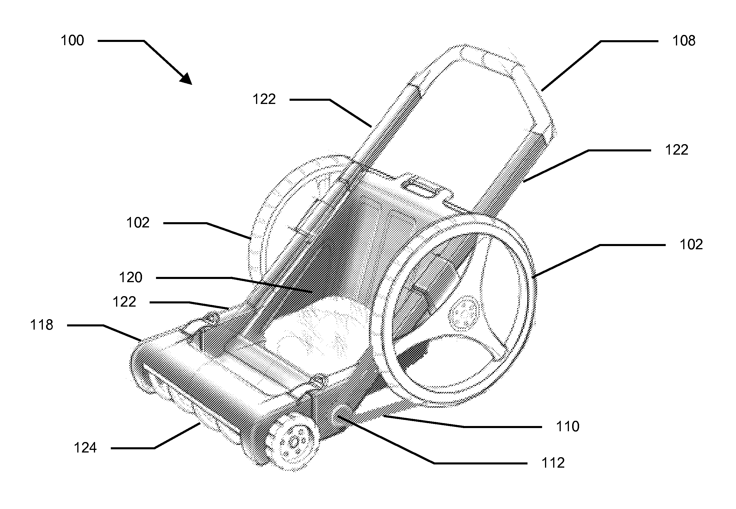
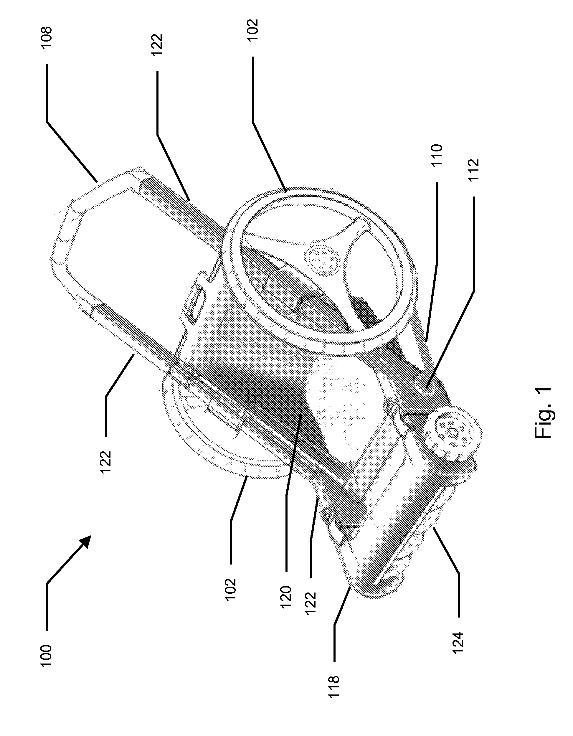
[0026] A modular landscaper may be operated by an operator. The operator may be responsible for providing forces required to operate the modular landscaper. Operating the modular landscaper may include gripping a handle and pushing or pulling the modular landscaper over a surface. An operator may include an adult, child, male, female, trained animal such as a dog, horse, mule, ox, and the like. The operation may be automated, such as may be provided by a robotic operator. The robotic operator may be fully automated, semi-automated, remote controlled, and the like. Power for the robotic operator may be solar based, fossil fuel based, biofuel based, and the like. In an example, an adult may be positioned behind the modular landscaper with one or two hands pushing the modular landscaper forward as the adult walks behind. The adult may control the direction of motion of the modular landscaper by applying a greater force near the left or right side of the modular landscaper, thereby caus...


PUM


Abstract

A modular landscaper uses oversized wheels to generate torque for turning one or more of several interchangeable modular landscape maintenance attachments. The landscaper provides a handle configured in relationship to the landscaper frame to allow an adult to normally walk behind the landscaper while applying a forward force by pushing on the handle that results in the wheels of the landscaper rolling along a landscape maintenance surface and generating torque that is transferred through a drive train to the one or more attached landscaping maintenance attachments. A drive train uses the rotational energy of the wheels to increase the operator pushing force to operate the maintenance attachment. Interchangeable attachments facilitate using the landscaper for a wide variety of landscaping maintenance tasks.

Description

CROSS-REFERENCE TO RELATED APPLICATIONS [0001] This application claims the benefit of the following provisional application, which is hereby incorporated by reference in its entirety: [0002] U.S. Provisional Application No. 60 / 838,099, filed Aug. 15, 2006.BACKGROUND [0003] 1. Field [0004] The methods and systems of wheeled landscape maintenance disclosed herein relate to landscape maintenance apparatus. In particular, the methods and systems relate to improved methods and systems of converting torque to enable a landscape maintenance function. [0005] 2. Description of the Related Art [0006] Many separate devices are used to accomplish the daily and seasonal tasks around the exterior of the home. For example, during the summer we use lawn mowers, edger trimmers, seed broadcasters, and the like. During the fall we use leaf blowers, leaf collectors, fertilizer spreaders, and the like. During the winter we use snow blowers, salt spreaders, motorized walkway snow brushes, and the like. A...

Claims


Application Information

Patent Timeline
IPC IPC(8): A01D34/54A01D42/06A01D34/00A01B76/00E01H5/00
CPCA01B45/02A01C7/02A01G1/12A01D42/00A01C15/02A01G20/30
Inventor DAYTON, DOUGLAS C.PARK, SUNG
Owner UMAGINATION LABS
Why Eureka
Try Eureka