Sample holder for NMR measurements with field homogenization in the sample volume by means of the bordering surfaces of the sample holder

a sample holder and sample volume technology, applied in the direction of magnetic resonance, acoustic wave reradiation, measurement devices, etc., can solve the problems of poor signal-to-noise ratio, poor measurement results, and weak closing section, so as to improve the quality of nmr measurements and enhance the compensatory effect

Active Publication Date: 2008-05-08
BRUKER SWITZERLAND AG
View PDF16 Cites 13 Cited by
  • Summary
  • Abstract
  • Description
  • Claims
  • Application Information

AI Technical Summary

Benefits of technology

[0026]In a further preferred embodiment, |F1+F2|≦0.5·10−6 and, in particular, |F1+F2|≦0.1·10−6 apply throughout the sample volume. This also ensures an enhanced compensatory effect that further improves the quality of the NMR measurements.
[0027]In an especially preferred embodiment, the following applies: χ2χ3>0 and |χ2|>|χ3| in particular, where |χ2|.|χ3|>1.1. These relations can easily be achieved by a suitable choice of material for the sample vessel. If these relations are adhered to, sufficient and opposite field changes due to the inner and outer interfaces are easily achieved.

Problems solved by technology

Inside, the sample vessel generally distorts the magnetic field that is homogeneous and static outside, potentially resulting in measurement results of poorer quality.
Whereas the section having the shape of a cylinder envelope causes only minor distortions, the closing section can produce strong field distortions.
Thus, only a small part of the available mass of the sample is actually measured, which results in a poorer signal-to-noise ratio.
However, in this case, the inner interface between the sample vessel and the measurement sample (usually a liquid sample) can cause magnetic field distortions in the sample volume.
However, it is difficult and expensive to adjust the susceptibility of the material of the sample vessel.

Method used


Image

  • Sample holder for NMR measurements with field homogenization in the sample volume by means of the bordering surfaces of the sample holder
  • Sample holder for NMR measurements with field homogenization in the sample volume by means of the bordering surfaces of the sample holder
  • Sample holder for NMR measurements with field homogenization in the sample volume by means of the bordering surfaces of the sample holder

Examples


Embodiment Construction

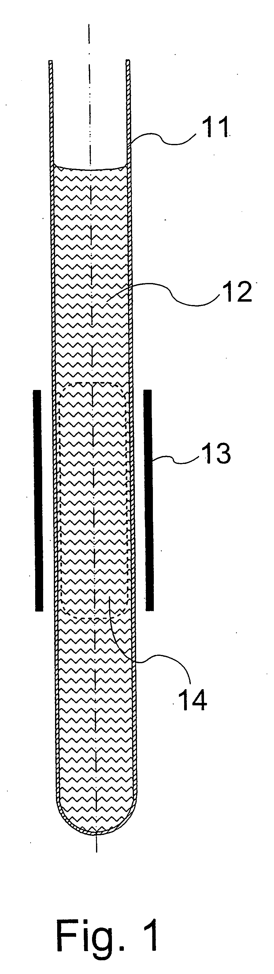
[0062]FIG. 1 shows a longitudinal section through the typical shape of a sample vessel used in high-resolution NMR spectroscopy (11) that is filled with a sample substance (12). The three-dimensional geometry of the vessel must be thought of as being rotationally symmetrical around the axis indicated by the, dot-and-dash line. A radial section through the RF coil (13) outside the sample vessel is indicated. The extent of the RF coil in the longitudinal direction determines the portion of the volume (14) of the liquid to be analyzed that will contribute to the NMR signal. The extent of this portion of the volume (measured region) (14) is indicated by a dashed line. The sample vessel shape shown here is used if a sufficient quantity of sample substance is available.

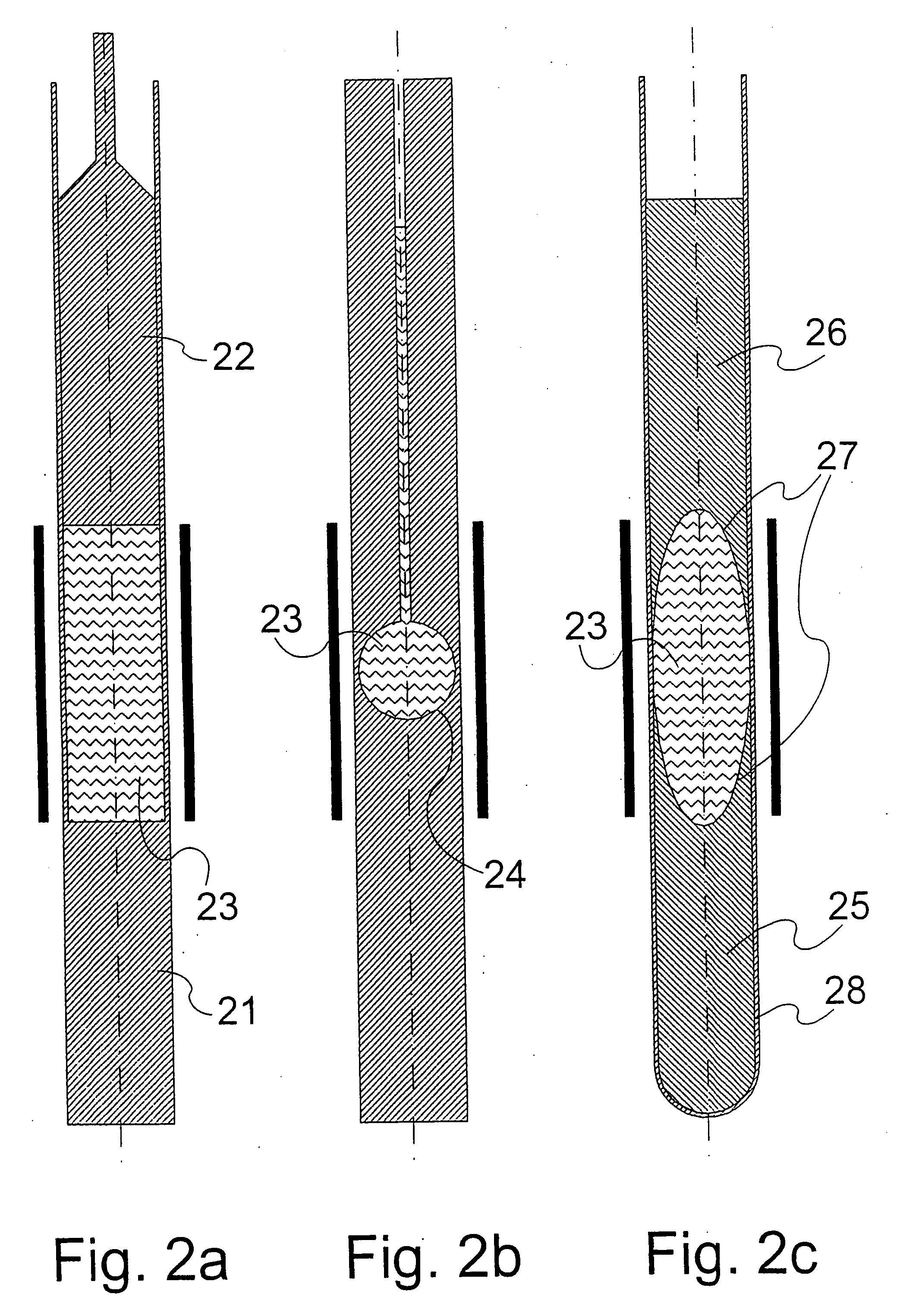
[0063]FIG. 2 shows a longitudinal section through known sample vessels that permit a reduced volume of liquid without causing a magnetic field inhomogeneity inside the sample volume.

[0064]FIG. 2a shows a sample vessel accor...


PUM


Abstract

A sample vessel (80) made of material with magnetic susceptibility χ2, for containing a sample substance (87) with magnetic susceptibility χ3≠χ2 to be analyzed in a nuclear magnetic resonance (NMR) spectrometer, has an inner interface G2 toward the sample substance and an outer interface G1 toward the environment (85) that exhibits magnetic susceptibility χ1. The shape of the interface toward the sample substance and the interface toward the environment are coordinated to match the discontinuities in susceptibility at the interfaces in such a way that on introduction of the sample tube filled with sample substance into the previously homogeneous magnetic field of an NMR spectrometer, the magnetic field inside the sample substance remains largely homogeneous.

Description

This application claims Paris Convention priority of DE 10 2006 052 076.9 filed Nov. 04, 2006 the complete disclosure of which is hereby incorporated by reference.BACKGROUND OF THE INVENTION[0001]The invention relates to a sample vessel for NMR measurements, comprising a vessel material of magnetic susceptibility χ2,[0002]with an outer interface that delimits the sample vessel with respect to the environment,[0003]and with an inner interface that delimits the sample vessel with respect to the sample volume, wherein the outer interface comprises[0004]an outer cylindrical surface that is a cylinder envelope whose axis of symmetry is aligned parallel with a z-direction,[0005]and an outer closing surface that closes the bottom of the sample vessel and is joined to the outer cylindrical surface,[0006]wherein the inner interface comprises[0007]an inner cylindrical surface that is a cylinder envelope whose axis of symmetry is aligned parallel with the z-direction,[0008]and an inner closing...

Claims


Application Information

Patent Timeline
Patent Type & Authority Applications(United States)
IPC IPC(8): G01R33/30
CPCG01R33/56536G01R33/30
Inventor FEY, MICHAELSPECK, THOMAS
Owner BRUKER SWITZERLAND AG
Why Eureka
Try Eureka