Programmable cable with deskew and performance analysis circuits

a technology of performance analysis and programmable cables, applied in the direction of transmission, instruments, electric digital data processing, etc., can solve the problems of compromising channel quality, increasing the risk of misinterpreting the received data at the receiver end of the cable, and affecting the quality of the channel, so as to improve the quality of the preprocessed data signal

Active Publication Date: 2008-05-08
REDMERE TECH
View PDF17 Cites 65 Cited by
  • Summary
  • Abstract
  • Description
  • Claims
  • Application Information

AI Technical Summary

Benefits of technology

[0078]In the embodiments of the invention, the performance analysis circuitry includes: a differential to single-ended block for converting the boosted signal to a single-ended signal; a linear phase compensator to phase-align the single-ended signal with a common clock signal; an oversampling circuit providing a digital representation of the phase-aligned single ended signal to produce a preprocessed data signal; and a training function circuit for estimating a quality of the preprocessed data signal, and adjusting the parameters of the deskew and equalizer circuits by changing the adjustable parameters to improve the quality of the preprocessed data signal.

Problems solved by technology

The inherent characteristics and manufacturing imperfections of high-speed differential signaling cables such as may be used to carry HDMI signals have an adverse effect on the high-speed signals carried by the cable.
This leads to an increased risk of misinterpreting the received data at the receiver end of the cable, especially for long cables and high-speed data.
This reduction is seen as a closure of the receive data eye and directly compromises the channel quality.
Earlier approaches to improving cable quality so far have been limited to embedded passive equalizer circuits within the cable, which boost high frequencies of the signals attenuated in the cable.
As a result, they cannot be embedded in a standard HDMI cable.
The possibility of embedding an active device within the cable is associated with a problem.
Firstly, no power input may be available for such a device except through the cable, i.e. there is no provision for external power supplies.
Secondly, in the case of the HDMI cable, there is not enough power available to power a simple signal regenerator, primarily because of the specification requirement to provide a termination voltage for the inputs.
As a result, the embedded active device apparently cannot be powered as required.
Unfortunately, these requirements cannot be met in a standard HDMI cable in a simple way.

Method used


Image

  • Programmable cable with deskew and performance analysis circuits
  • Programmable cable with deskew and performance analysis circuits
  • Programmable cable with deskew and performance analysis circuits

Examples


Embodiment Construction

[0135]FIG. 3 shows a prior art HDMI (High-Definition Multi-Media Interface) system, including a HDMI transmitter Tx (HDMI Source Device), a HDMI receiver Rx (HDMI Sink Device), and an HDMI cable connecting the Tx and the Rx.

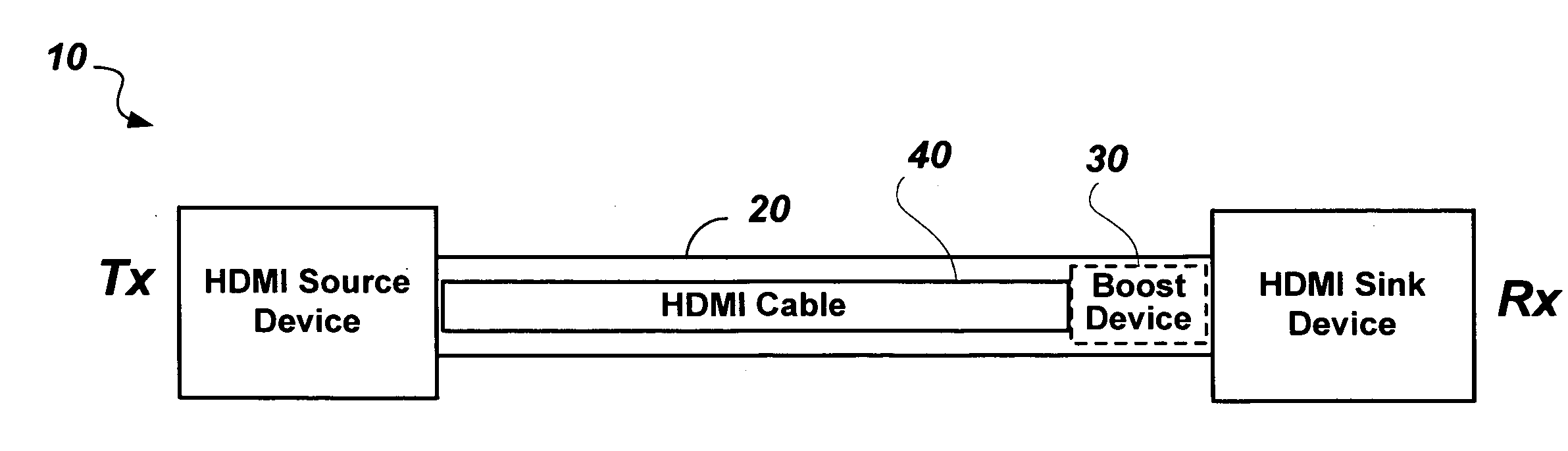
[0136]FIG. 4 shows an HDMI system 10 including an improved HDMI cable 20 according to an embodiment of the present invention.

[0137]The HDMI system 10 includes the HDMI transmitter Tx (HDMI Source Device), the HDMI receiver Rx (HDMI Sink Device), and the improved HDMI cable 20 of the embodiment of the present invention, connecting the Tx and Rx.

[0138]The improved HDMI cable 20 comprises an embedded boost device 30, details of which are described in the following, and a basic (passive) HDMI cable 40. The boost device 30 is located near the end of the improved HDMI cable 20 closest to the HDMI receiver Rx. Without limiting the generality of the application, the improved HDMI cable 20 may be used to connect a DVD player (an example of an HDMI Source Device) to a Tele...


PUM


Abstract

An HDMI cable carries high speed encoded data which are transmitted differentially over data channels, along with a clock. High-frequency loss and differential skew within a differential signal may be compensated by analog circuits embedded in the cable. These embedded circuits are tuned at production for best performance by observing the quality of the recovered analog signal. The embedded circuits are powered by a combination of power sources, both carried within the cable, and harvested from the high-speed signals themselves.

Description

FIELD OF THE INVENTION[0001]The present invention relates to high speed cables that carry serially encoded differential signals between electronic equipments, and in particular, multi-conductor cables interconnecting audio-visual equipment.BACKGROUND OF THE INVENTION[0002]The distribution of television signals has increasingly become based on digital methods and digitally encoded forms of video and audio signals. At the same time, higher resolution (high definition TV) has become available in the market place, commensurate with larger and higher definition displays. To meet the requirement of interconnecting such high definition displays with digital signal sources such as Digital Versatile Disc (DVD) players and receivers / decoders for digital satellite and digital cable distribution of video material, a digital interface standard has evolved, known as the High-Definition Multimedia Interface (HDMI). A detailed specification for HDMI can be obtained from the “hdmi.org” website. The ...

Claims


Application Information

Patent Timeline
Patent Type & Authority Applications(United States)
IPC IPC(8): H03K5/01
CPCH04L25/02H04L25/242H04L25/03885
Inventor KEADY, AIDAN GERARDKEANE, JOHN ANTHONYREA, JUDITH ANNGRIFFIN, BENJAMINHORAN, JOHN MARTIN
Owner REDMERE TECH
Why Eureka
Try Eureka