
Switching power supply unit and method for setting switching frequency

a technology of switching power supply and frequency, applied in the field of power, can solve the problems of increasing power consumption, poor response, and dropping xb>1/b> in output, and achieve the effects of improving the stability at the start time, smooth shifting to the high frequency, and improving the response of frequency switching timing

Inactive Publication Date: 2008-05-08
ECOPOWER DESIGN
View PDF7 Cites 8 Cited by
  • Summary
  • Abstract
  • Description
  • Claims
  • Application Information

AI Technical Summary

Benefits of technology

[0016]It is an object of the present invention to provide a switching power supply unit which reduces a drop in output on such occasions as during start-up and when shifting to a high frequency, with stable rising waveforms even under light load. Another object of the present invention is to provide a power saving circuit with a reduced parts count and smaller power consumption, and a switching power supply unit which uses this power saving circuit.
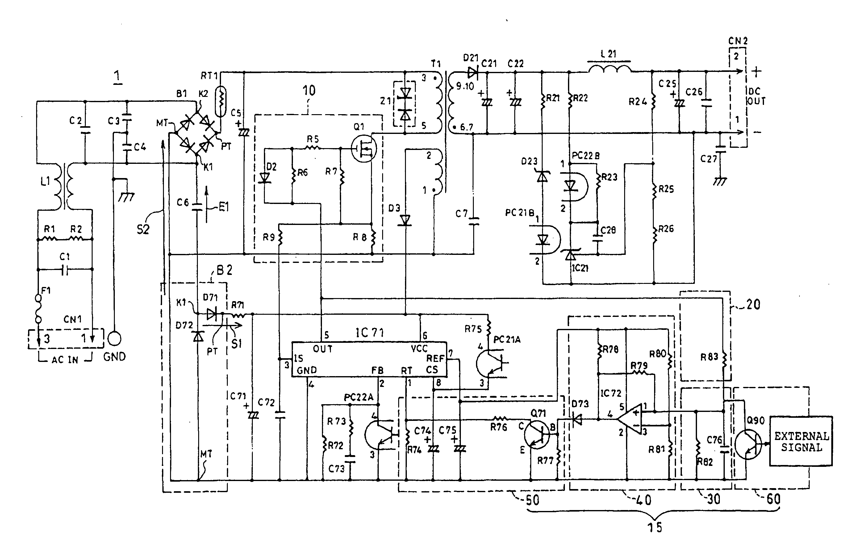
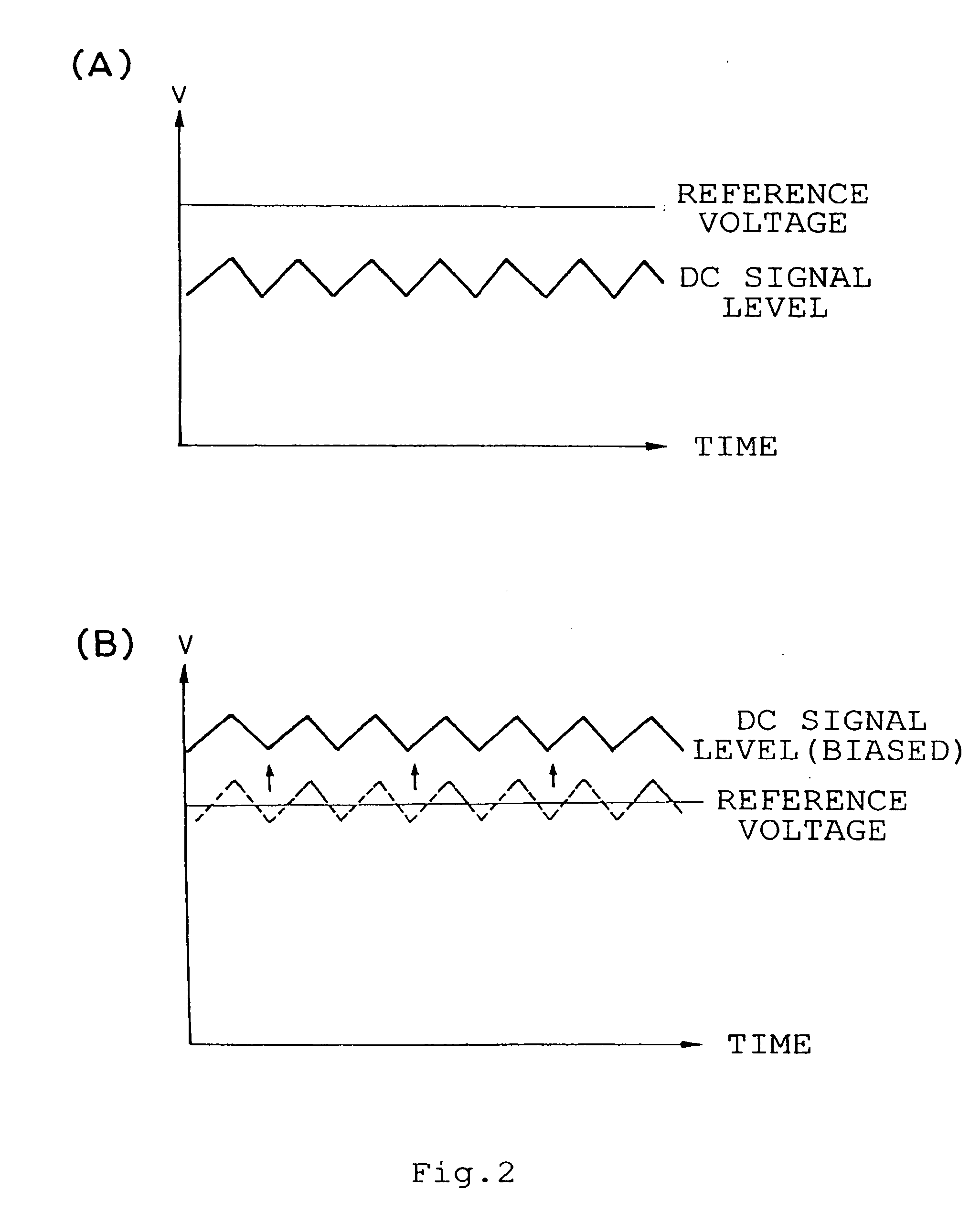
[0020]In the switching power supply unit according to the first aspect of the present invention, the frequency switching unit may include an output detection circuit for detecting the pulse output of the switching circuit, a DC signal level conversion circuit for converting the pulse output detected by the output detection circuit into a DC signal level, a comparison circuit for comparing the DC signal level converted by the DC signal level conversion circuit with a reference voltage, and a resistance changing circuit for changing a resistance of a resistor based on the result of comparison by the comparison circuit, thereby switching the frequency of the switching signal in the pulse oscillator circuit. In this instance, the resistance changing circuit may reduce the resistance of the resistor to increase the frequency of the switching signal when the DC signal level reaches the reference voltage.
[0033]According to the present invention, the frequency switching unit changes the resistance by use of a resistor. This improves the response of the frequency switching timing and, in particular, makes it possible to smoothly shift to the high frequency when starting-up. The use of the resistor in the frequency switching unit also makes it possible to start the switching signal with a low frequency. This improves the stability at start time, and can reduce the power consumption.
[0034]Moreover, according to the present invention, the half-wave rectifier means makes it possible to form the power saving circuit or the switching power supply unit in a simple configuration with a lower parts count. This can reduce the manufacturing costs. In addition, the one single series capacitor introduces the current to the first diode through the single AC terminal for half-wave rectification, and the second diode discharges this series capacitor in order to prepare for the next half-wave rectification in a short time. This allows efficient rising with a small time constant. Since the frequency switching unit uses the resistor to change the resistance for frequency switching, it is possible to start with a low frequency. The power consumption can thus be reduced when the pulse oscillator circuit repeats the start-up.

Problems solved by technology

Consequently, a problem has existed in that switching from the high frequency H to the low frequency L occurs even under light load, causing a drop X1 in output.
Starting with the high frequency H has also resulted in the problem of increased power consumption.
Moreover, since the frequency switching circuit 14 is configured to use the capacitors C17 and C2 for frequency switching, there has been a problem of poor response, which is ascribable to the charging and discharging operations.
As a result, the output voltage becomes high enough before the switching frequency is switched from the low frequency L to the high frequency H. This causes a large drop X2 in the output capacity upon switching, with the problem that smooth output characteristics cannot be obtained.
There has conventionally been another problem in that the second bridge rectifier D2 is composed of four diodes, i.e., with a high parts count and a large circuit size.
Introducing the alternating current into this second bridge rectifier D2 requires two series capacitors C3 and C6, which also contributes to the problem of an increased parts count.
There has also been the problem that these components consume power.
There has thus been the problem of increased power consumption in standby mode.
Since this circuit is designed so that the pulse oscillator circuit IC1 repeats the ON (start-up) and OFF (stop) operations at regular intervals when in standby mode (power saving mode), starting with a high frequency upon each start-up has produced the problem of increased power consumption.

Method used


Image

  • Switching power supply unit and method for setting switching frequency
  • Switching power supply unit and method for setting switching frequency
  • Switching power supply unit and method for setting switching frequency

Examples


Embodiment Construction

[0043]Hereinafter, a preferred embodiment of the present invention will be described in detail with reference to the drawings.

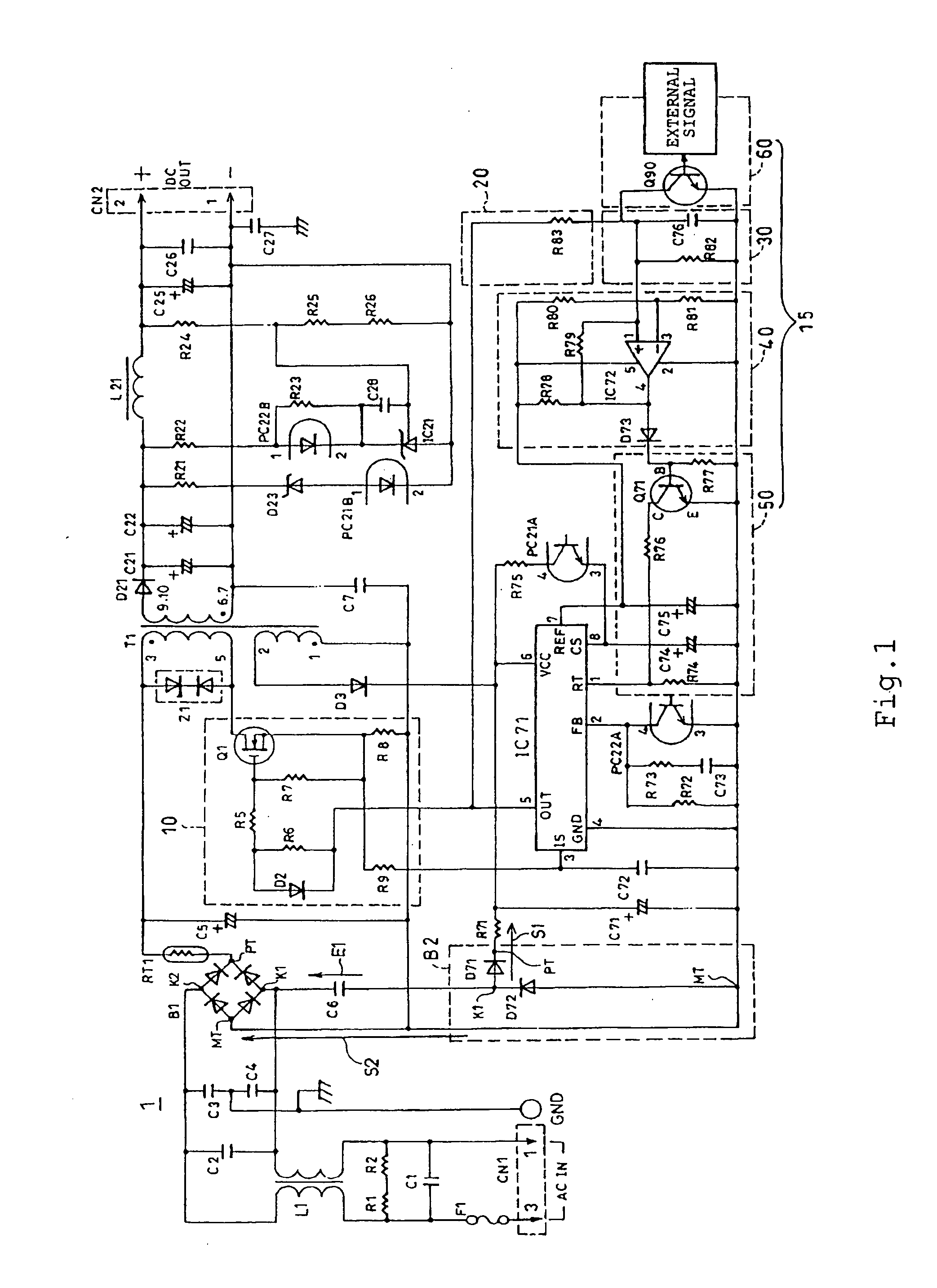
[0044]FIG. 1 is a circuit diagram showing a switching power supply unit 1 which uses a power saving circuit according to one embodiment of the present invention. The switching power supply unit 1 includes an AC power source CN1, a first full-wave bridge rectifier B1 and a second half-wave rectifier circuit B2, a switching circuit 10, a transformer T1, a pulse oscillator circuit IC71, and frequency switching unit 15. The first full-wave bridge rectifier B1 and the second half-wave rectifier circuit B2 are connected to the AC power source CN1, and rectify the alternating current into direct currents. The switching circuit 10 switches the current rectified by the first full-wave bridge rectifier B1. The transformer T1 steps the voltage up or down depending on the direct current switched by the switching circuit 10. The pulse oscillator circuit IC71 outputs a swi...


PUM


Abstract

A switching power supply unit is provided which provides improved response for frequency switching with a smooth rise in voltage. The switching power supply unit includes: a rectifier circuit for rectifying an alternating current from an AC power source into a direct current; a switching circuit for switching the current rectified by this rectifier circuit using a switching device; a pulse oscillator circuit for outputting a switching signal to the switching device; and a transformer circuit for stepping a voltage up or down depending on the current switched by this switching circuit. A frequency switching unit is also used to detect a pulse output from the switching circuit. Based on the state of this pulse output, the frequency switching unit changes a resistance using resistors, thereby switching the frequency of the switching signal in the pulse oscillator circuit.

Description

BACKGROUND OF THE INVENTION[0001]1. Field of the Invention[0002]The present invention relates to a power saving circuit for reducing the standby power and start-up power of an electric apparatus, a switching power supply unit for exercising control using a switching device, and a method for setting a switching frequency of a switching power supply unit.[0003]2. Description of the Related Art[0004]Power saving circuits for reducing the standby power and the like of electrical equipment have been widely used, for example, as switching power supply units. FIG. 6 shows the circuitry of a conventional switching power supply unit. This switching power supply unit includes such components as an AC power source CN1, a first bridge rectifier D1, a main switching device Q1, a transformer T1, and a pulse oscillator circuit IC1. The first bridge rectifier D1 is connected to the AC power source CN1. The transformer T1 has a primary winding and a secondary winding, and functions as a transformer ...

Claims


Application Information

Patent Timeline
Patent Type & Authority Applications(United States)
IPC IPC(8): H02M3/335H02M1/36
CPCH02M1/36Y02B70/16H02M2001/0032H02M3/33507Y10S323/901Y02B70/10H02M1/0032H02M7/05
Inventor YAMAZAKI, YUKIO
Owner ECOPOWER DESIGN
Learn More