Air valve and method of use

a technology of air valve and air valve body, which is applied in the direction of engine controllers, electric control, machines/engines, etc., can solve the problems of complex and cumbersome design of air valves, difficult to fit into applications, and insufficient reliability of brush-type permanent magnet motors

Inactive Publication Date: 2008-05-15
NAVISTAR
View PDF33 Cites 22 Cited by
  • Summary
  • Abstract
  • Description
  • Claims
  • Application Information

AI Technical Summary

Benefits of technology

[0010]Moreover, the prior art includes complex and cumbersome designs for air valves and sensors that are difficult to fit into applications because of size, weight, and other considerations. Therefore, a need exists for a compact, efficient packaged design that allows for use in a variety of applications.

Problems solved by technology

Brush type permanent magnet motors do not maintain a sufficient reliability because of a relatively short life expectancy.
This device is also subject to reliability issues because of a relatively short life expectancy.
Moreover, the prior art includes complex and cumbersome designs for air valves and sensors that are difficult to fit into applications because of size, weight, and other considerations.

Method used


Image

  • Air valve and method of use
  • Air valve and method of use
  • Air valve and method of use

Examples


Embodiment Construction

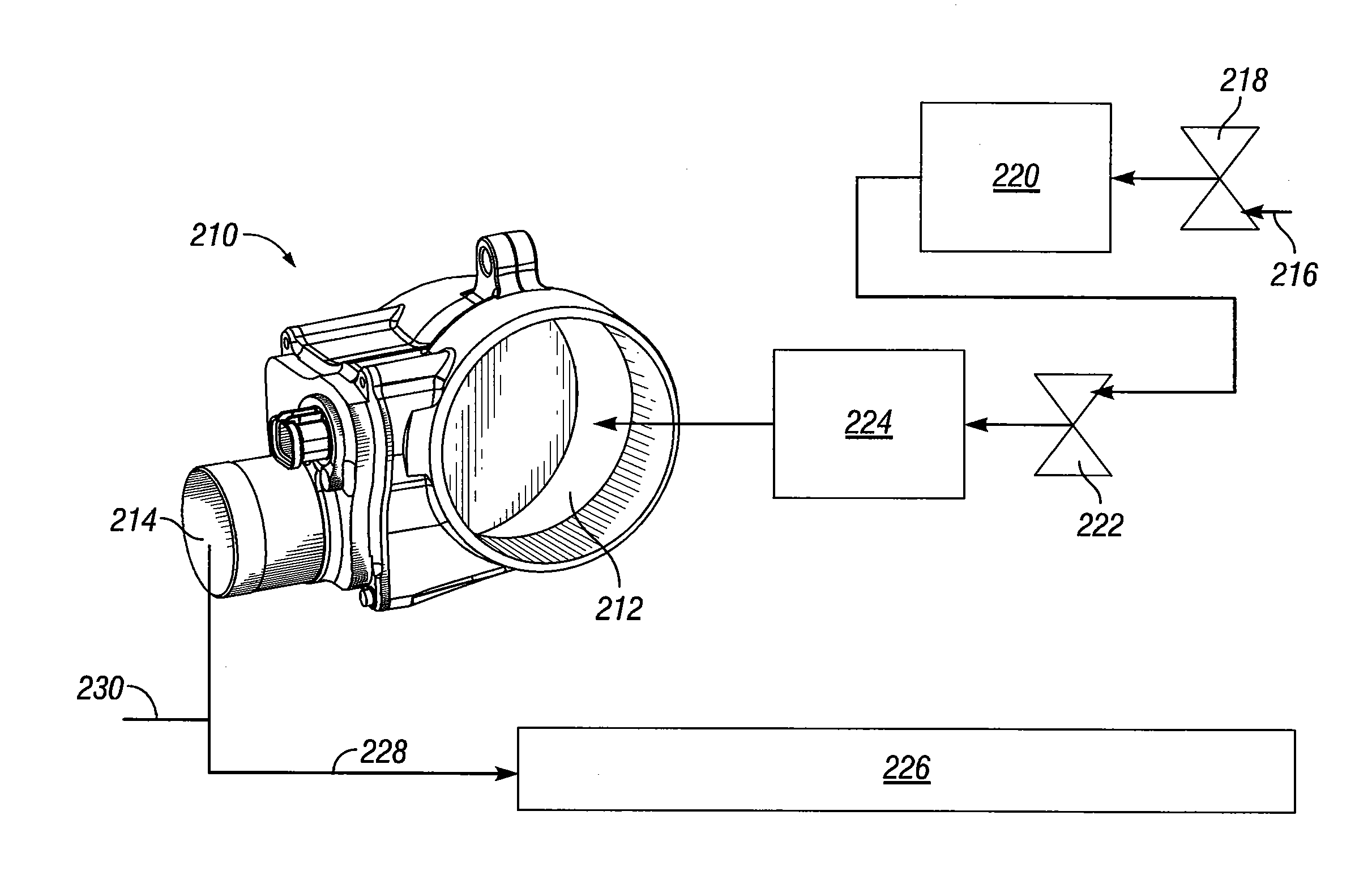
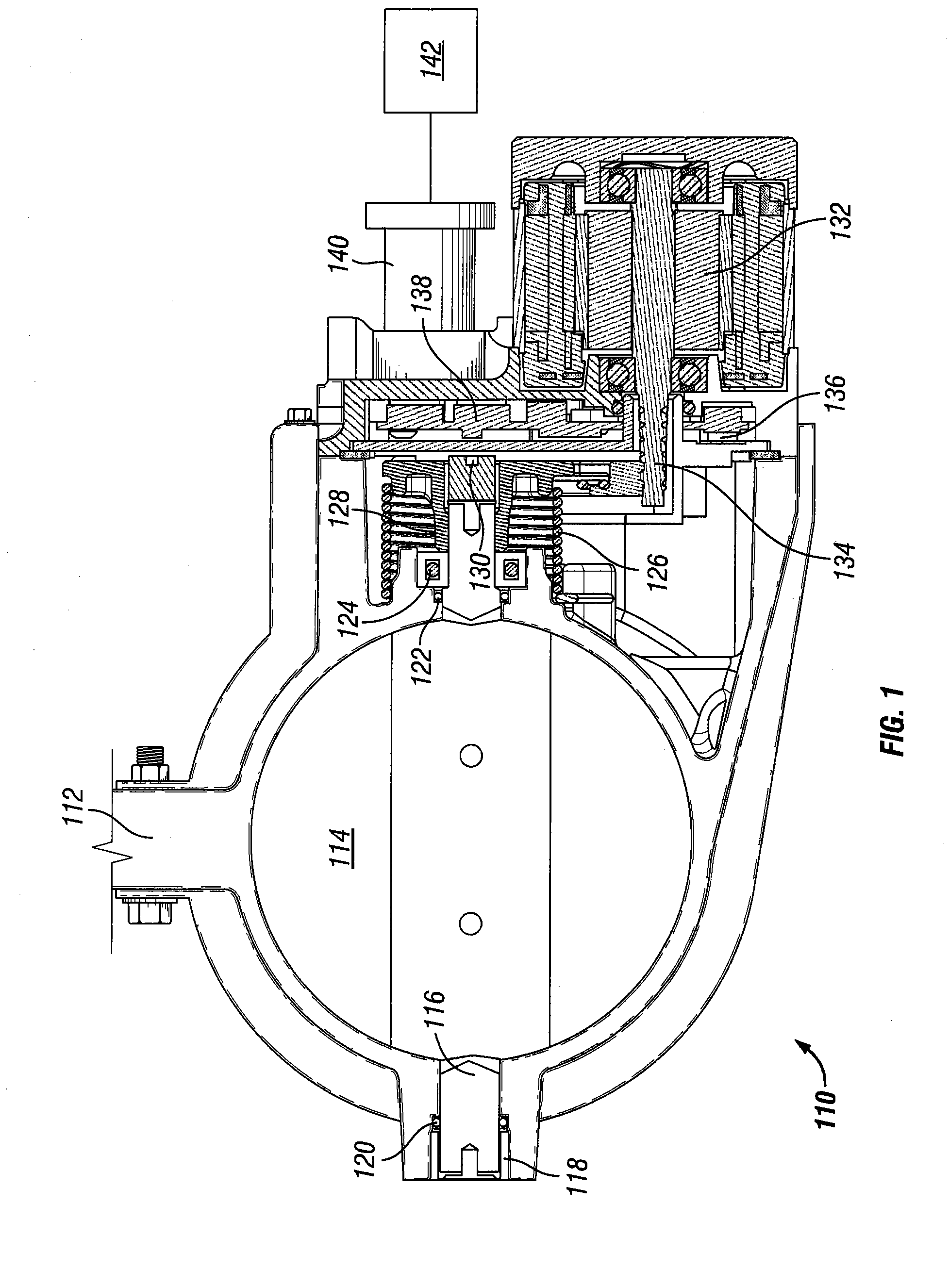
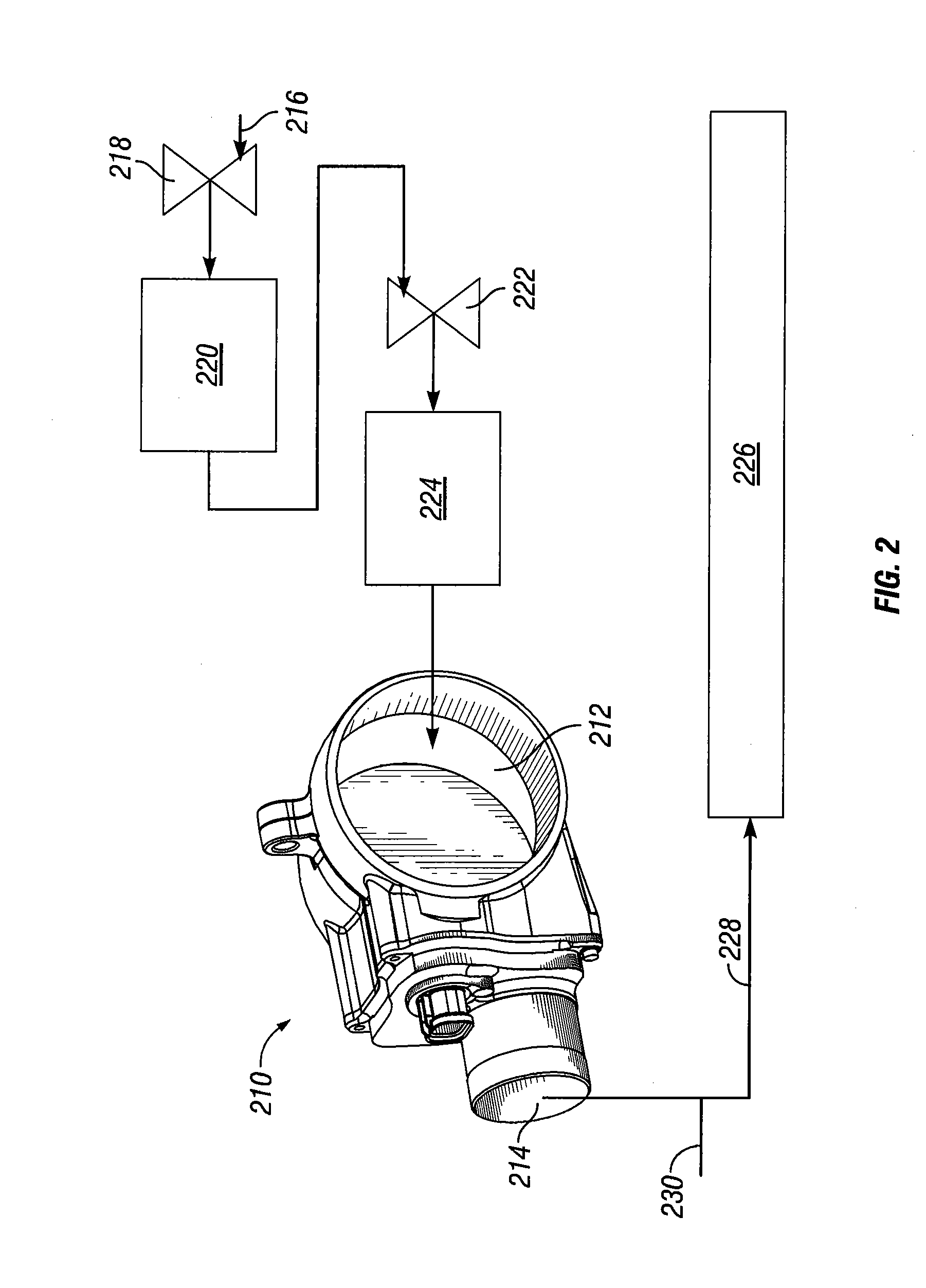
[0020]One or more illustrative embodiments incorporating the invention disclosed herein are presented below. Not all features of an actual implementation are described or shown in this application for the sake of clarity. It is understood that in the development of an actual embodiment incorporating the present invention, numerous implementation-specific decisions must be made to achieve the developer's goals, such as compliance with system-related, business-related, government-related and other constraints, which vary by implementation and from time to time. While a developer's efforts might be complex and time-consuming, such efforts would be, nevertheless, a routine undertaking for those of ordinary skill in the art having benefit of this disclosure. The present invention is designed to provide enhanced engine exhaust emission management. In a preferred embodiment, the air valve features a package optimized aluminum body with a single electric connection. The air valve can be use...


PUM


Abstract

An air valve and its method of use including an air valve housing; a throttle plate disposed on a throttle shaft; a driven gear attached on the throttle shaft; a brushless direct current motor assembly in connection via a pinion with the driven gear; an integrated electronic valve controller including digital signal processing on a circuit board; and a throttle position sensor on the circuit board, wherein the throttle position sensor includes at least one non-contact type sensor. In a preferred embodiment, the air valve includes an inlet port and an outlet port connected to an engine via an air intake manifold, such that re-circulated exhaust gas is introduced into the air intake manifold.

Description

CROSS REFERENCE TO RELATED APPLICATIONS[0001]This application is a continuation-in-part of U.S. patent application Ser. No. 11 / 559,067, filed Nov. 13, 2006.STATEMENT REGARDING FEDERALLY SPONSORED RESEARCH OR DEVELOPMENT[0002]Not applicable.REFERENCE TO APPENDIX[0003]Not applicable.FIELD OF THE INVENTION[0004]This disclosure relates to control systems and more particularly to an electronic control system for engines.BACKGROUND OF THE INVENTION[0005]The prior art includes technology for spark ignition engine that achieved air management via electronic controls. Air flow management devices for engine applications have historically used brush type permanent magnet motors and pulse width modulation speed control. Brush type permanent magnet motors do not maintain a sufficient reliability because of a relatively short life expectancy. Therefore a need exists for the use of brushless motors.[0006]Due to the low life expectancy of brush type DC motors, some original equipment (OE) companies...

Claims


Application Information

Patent Timeline
Patent Type & Authority Applications(United States)
IPC IPC(8): F02D11/10
CPCF02D11/106F02D2200/0404F02D2041/285F02D41/0077
Inventor BAASCH, OSWALDTEDDER, ROY E.ATTARSEYEDI, SIAMAKBRANDT, JARED A.GERBER, NEAL R.JANES, NIGEL C.LINDSEY, JASPER C.BIGLEY, JON A.
Owner NAVISTAR
Why Eureka
Try Eureka