Compensation for leakage current variation by the utilization of an automatic self-adaptive keeper

a technology of leakage current variation and automatic self-adaptive keeper, which is applied in the direction of pulse technique, process and machine control, instruments, etc., can solve the problems of reducing the standby time of portable devices, consuming power, and sacrificing too much performance, so as to reduce the leakage effect and achieve optimal current strength

Inactive Publication Date: 2008-05-15
IBM CORP
View PDF7 Cites 16 Cited by
  • Summary
  • Abstract
  • Description
  • Claims
  • Application Information

AI Technical Summary

Benefits of technology

[0007]Disclosed is a method and system for automatically detecting and optimally compensating a wide range of die leakage currents in dynamic circuits. A self-adaptive keeper tracks current leakage and reduces the leakage effects by optimally controlled compensation current. The self-adaptive keeper utilizes a 2-stage embedded current mirror circuit, a dummy cell and a self-adaptive keeper transistor to compensate leakage current. The load impact of the self-adaptive keeper circuitry on static and dynamic circuit components (such as, the impact on memory cells, for example) is minimized by the dummy cell. The dummy cell is essentially a leakage current monitor device, which detects and matches the instant leakage current from the dynamic circuit components. Leakage amplification by the 2-stage current mirror circuit provides an optimal current strength in the keeper transistor. The amplification level is determined by the size of the transistors within the leakage current path of the 2-stage current mirror circuit. In the pre-charge phase, the keeper transistor allows the passage of the amplified leakage current. This optimally amplified leakage current is utilized to compensate for a leakage induced voltage drop at the circuit's output. Thus, the self-adaptive keeper ensures the robustness of the circuit in real time.

Problems solved by technology

In Integrated circuit (IC) fabrication technology, lower threshold voltages and smaller transistor geometry result in higher leakage current, which is defined as the current passing through a transistor when it is turned off.
Leakage current consumes power and reduces standby time for portable devices that use battery power.
Consequently, reducing leakage current without sacrificing too much performance is one of the major challenges in IC designs.
Leakage current is more problematic as IC circuits become smaller.
This variation indicates that a large number of low leakage dies suffer from the performance loss due to an unnecessarily over sized keeper.
Unfortunately, the excess leakage dies still do not satisfy the robustness requirements with a keeper sized for the faster corner leakage.
This inability to satisfy performance requirements reveals the drawbacks of a conventional keeper used under a wide range of inter or intra-die variation.
Thus, the use of these globally-routed control signals is usually costly and time consuming.

Method used


Image

  • Compensation for leakage current variation by the utilization of an automatic self-adaptive keeper
  • Compensation for leakage current variation by the utilization of an automatic self-adaptive keeper
  • Compensation for leakage current variation by the utilization of an automatic self-adaptive keeper

Examples


Embodiment Construction

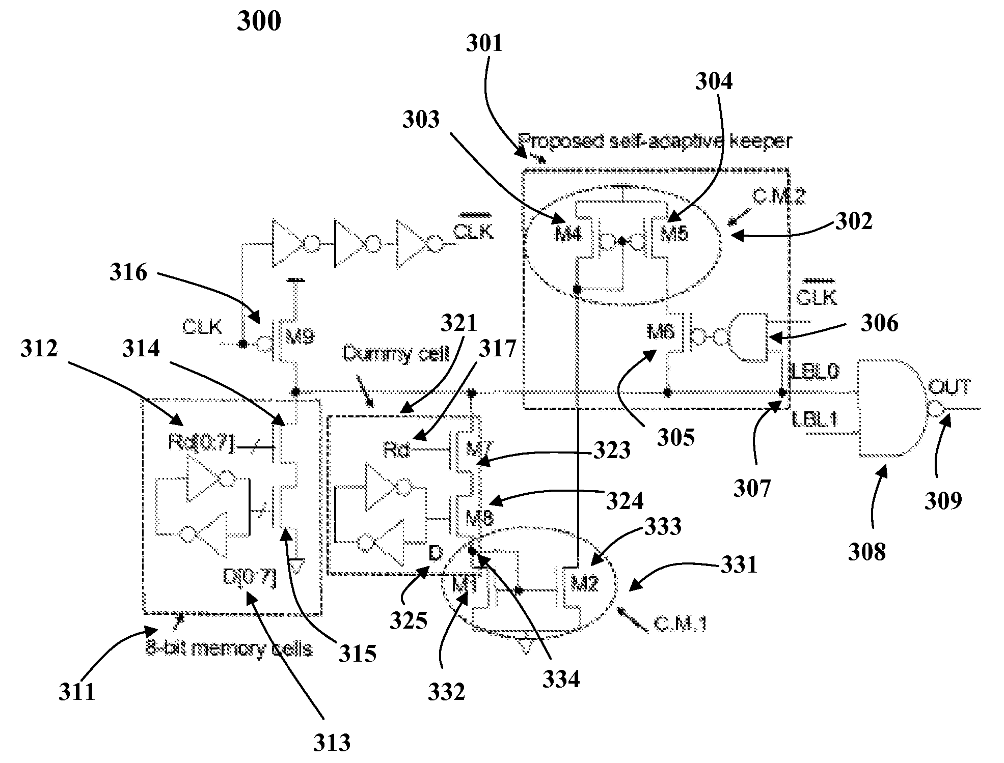
[0014]The present invention provides a method and system for automatically detecting and optimally compensating a wide range of die leakage currents in dynamic circuits. A self-adaptive keeper tracks current leakage and reduces the leakage effects by optimally controlled compensation current. The self-adaptive keeper utilizes a 2-stage embedded current mirror circuit, a dummy cell and a self-adaptive keeper transistor to compensate leakage current. The load impact of the self-adaptive keeper circuitry on static and dynamic circuit components (such as, the impact on memory cells, for example) is minimized by the dummy cell. The dummy cell is essentially a leakage current monitor device, which detects and matches the instant leakage current from the dynamic circuit components. Leakage amplification by the 2-stage current mirror circuit provides an optimal current strength in the keeper transistor. The amplification level is determined by the size of the transistors within the leakage ...


PUM


Abstract

A method and system for automatically detecting and optimally compensating a wide range of die leakage currents in dynamic circuits is presented. A self-adaptive keeper tracks the leakage and reduces the leakage effects by optimally controlled compensation current. The self-adaptive keeper utilizes a 2-stage embedded current mirror circuit, a dummy cell and a keeper transistor to compensate leakage current. The load impact of the self-adaptive keeper on the dynamic circuit components (for example, the impact on memory cells) is minimized by a dummy cell which detects and matches the instant leakage current. Amplification in the 2-stage embedded current mirror circuit provides an optimal current strength in the keeper transistor. The optimally amplified leakage current is utilized to compensate for a leakage induced voltage drop at the circuit's output. Thus, the self-adaptive keeper ensures the robustness of the circuit in real time and does not create any negative trade-off on read latency.

Description

BACKGROUND OF THE INVENTION[0001]1. Technical Field[0002]The present invention generally relates to integrated circuits and in particular to leakage current in integrated circuits. Still more particularly, the present invention relates to compensation of leakage current in integrated circuits.[0003]2. Description of the Related Art[0004]In Integrated circuit (IC) fabrication technology, lower threshold voltages and smaller transistor geometry result in higher leakage current, which is defined as the current passing through a transistor when it is turned off. Threshold voltage refers to the voltage at which transistors turn on. Leakage current consumes power and reduces standby time for portable devices that use battery power. Consequently, reducing leakage current without sacrificing too much performance is one of the major challenges in IC designs. Leakage current is more problematic as IC circuits become smaller. This is because leakage current increases at a high rate as transist...

Claims


Application Information

Patent Timeline
Patent Type & Authority Applications(United States)
IPC IPC(8): G05F1/10
CPCG11C11/417G01R31/3008
Inventor CHENG, ZHIBINKAPLUN, ALEKSANDR
Owner IBM CORP
Why Eureka
Try Eureka