Filter wheel

a filter wheel and wheel body technology, applied in the field of filter wheels, can solve the problems of difficult to effect the start-stoppage of the motor, and the inability to guarantee stable operation, so as to reduce the diameter of the third pulley, reduce the mass of the filter set table, and prevent the moment of inertia

Inactive Publication Date: 2008-05-15
YOKOGAWA ELECTRIC CORP
View PDF5 Cites 18 Cited by
  • Summary
  • Abstract
  • Description
  • Claims
  • Application Information

AI Technical Summary

Benefits of technology

[0022]When increasing the diameter of the filter set table as the size of the filter was changed, the third pulley was formed inside the space formed when the plurality of the filters were circularly disposed at equal intervals on the filter set table so as to be integral with the filter set table, and the belt was engaged with the respective outer peripheries of the first pulley, and the third pulley. As a result, it was possible to reduce the diameter of the third pulley, and to reduce the mass of the filter set table as compared with the case where the diameter of the first pulley was increased so as to match the size of the filter set table, so that an increase in load torque, and moment of inertia could be prevented.
[0023]Further, by combining the filter wheel with a stably operable motor, and adopting a three-step drive method, it was possible to implement quick changeover operation (for example, in 33 msec or less) of the filter set table with filters of a general-purpose filter size (for example, 25 mm in diameter) thereon.
[0024]Still further, while the teeth were formed on the respective outer peripheries of the first pulley, and the third pulley, the teeth were also formed on the inner periphery of the belt, and for material of the at least one of the first pulley, the third pulley, and the filter set table, use was made of either an aluminum alloy or plastics, so that it has become possible to execute fast operation without increasing a motor torque.

Problems solved by technology

In such a case, if the same motor is used, it will become harder to effect startup stoppage of the motor because load torque, and moment of inertia are proportional to mass.
Even if a motor with a larger torque is used, there has been a problem in that stable operation cannot be guaranteed under this condition.

Method used


Image

  • Filter wheel
  • Filter wheel
  • Filter wheel

Examples


Embodiment Construction

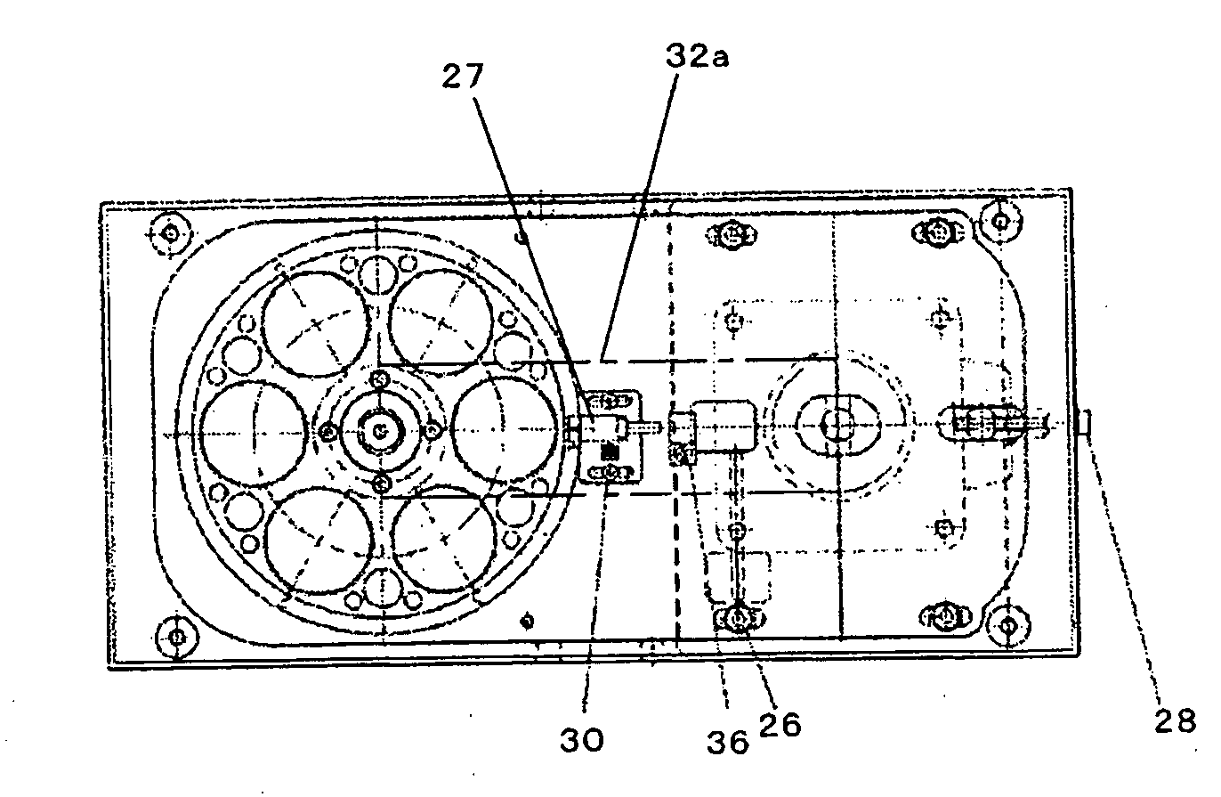
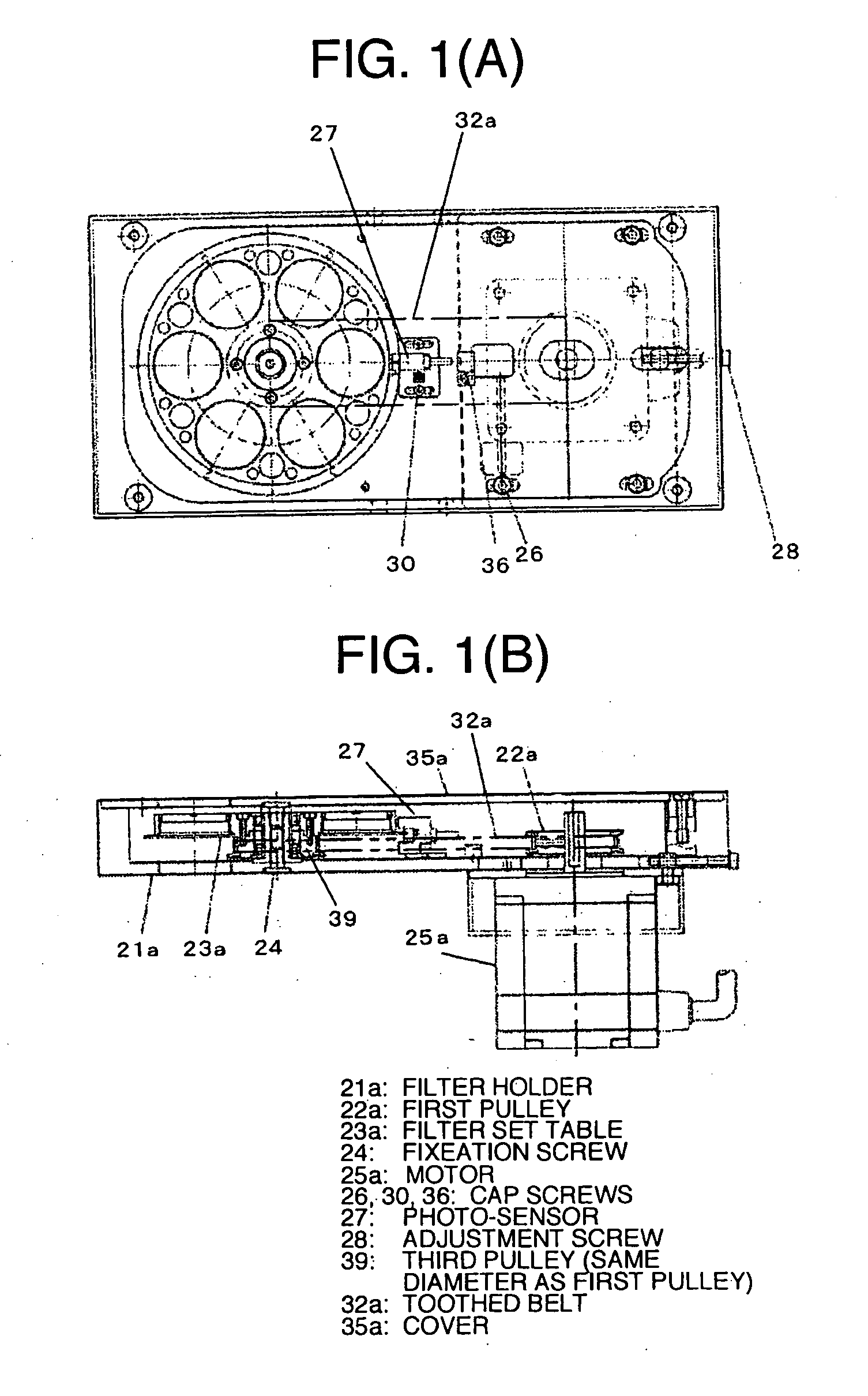
[0032]The invention is described in more detail hereinafter with reference to the accompanying drawings. FIG. 1 is a block diagram showing the principal part of one embodiment of a filter wheel according to the invention. In the figure, constituent elements identical to those in FIG. 7 are denoted by like reference numerals, thereby omitting duplicated description.

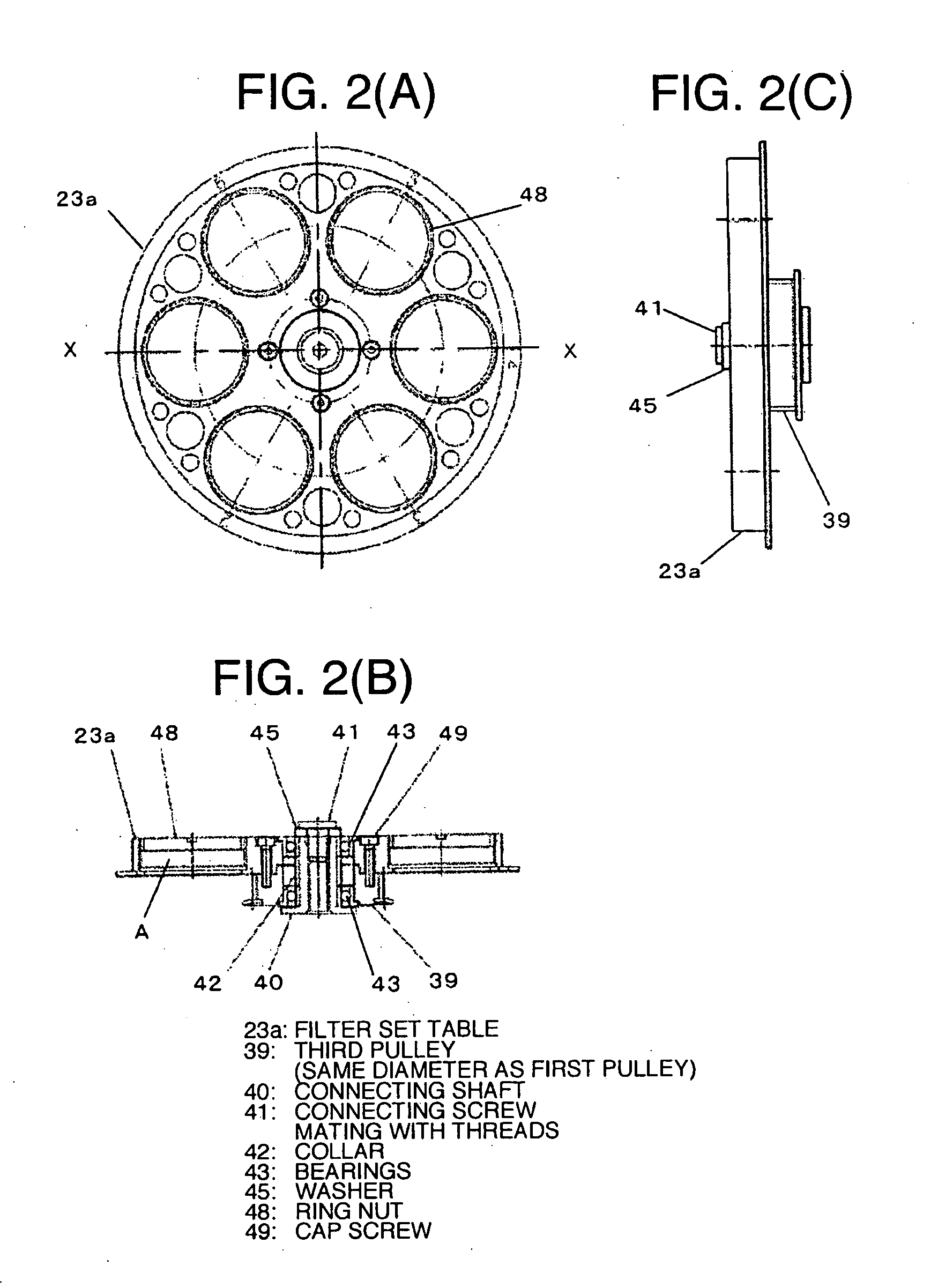
[0033]In FIG. 1, reference numeral 22a denotes a first pulley, and 39 a third pulley. The third pulley 39 is one corresponding to a case where respective diameters of filters mounted on a table 23a are increased in size from, for example, 18 mm to 25 mm. Further, the third pulley 39 is formed inside a space formed when a plurality of the filters (in the figure, 6 pieces of the filters 25 mm in diameter) are disposed in a circular fashion on the table 23a so as to be integral with the table 23a.

[0034]In this case, the diameter of the first pulley 22a is also changed so as to match that of the third pulley 39, and use is ma...


PUM


Abstract

A filter wheel capable of executing continuous operation accurately is implemented. The filter wheel comprises a first pulley fixed to a rotation axle of a motor, a filter set table (a second pulley) on which a plurality of filters circularly arranged at equal intervals between a center axis and an outer periphery thereof are mounted, and a belt engaged with respective outer peripheries of the first pulley, and the filter set table, for conveying rotation of the motor to the filter set table through the intermediary of the first pulley, wherein upon an increase in diameter of the filter set table, due to a change in size of the filter, a third pulley is formed inside a space formed when the plurality of the filters are disposed in a circular fashion on the filter set table so as to be integral with the filter set table, the belt being engaged with the respective outer peripheries of the first pulley, and the third pulley.

Description

FIELD OF THE INVENTION[0001]The invention relates to a filter wheel suitable for use in a confocal microscope comprising, for example, a microscope unit, and a confocal scanner unit, wherein excitation laser beams at a plurality of wavelengths are changed over by a excitation side filter means corresponding to the respective wavelengths before irradiating a specimen, and return fluorescent light beams from the specimen are caused to undergo image formation in an imaging means through the intermediary of a fluorescent observation side filter means capable of changing over the return fluorescent light beams so as to correspond to the respective wavelengths of the excitation laser beams.BACKGROUND OF THE INVENTION[0002]A confocal microscope of Nipkow disk method has been disclosed in detail in JP 5-60980 A.[0003]FIG. 6 is a functional block diagram showing a common system configuration of a confocal microscope by way of example. Reference numeral 1 denotes a multi-wavelength excitation...

Claims


Application Information

Patent Timeline
Patent Type & Authority Applications(United States)
IPC IPC(8): G02B5/22
CPCG02B7/006G02B26/008G02B21/0032
Inventor TANIBATA, YASUHIRONEZU, TAICHIROU
Owner YOKOGAWA ELECTRIC CORP
Why Eureka
Try Eureka