

Fuel cell
a fuel cell and fuel cell technology, applied in the field of fuel cells, can solve the problems of reactant gas not flowing smoothly, unsatisfactory sealing performance, and unsatisfactory sealing performance, and achieve the effect of simple and economical structure and effective simplifying the process of assembling the fuel cell
- Summary
- Abstract
- Description
- Claims
- Application Information
AI Technical Summary
Benefits of technology
Problems solved by technology
Method used
Image

Examples
first embodiment
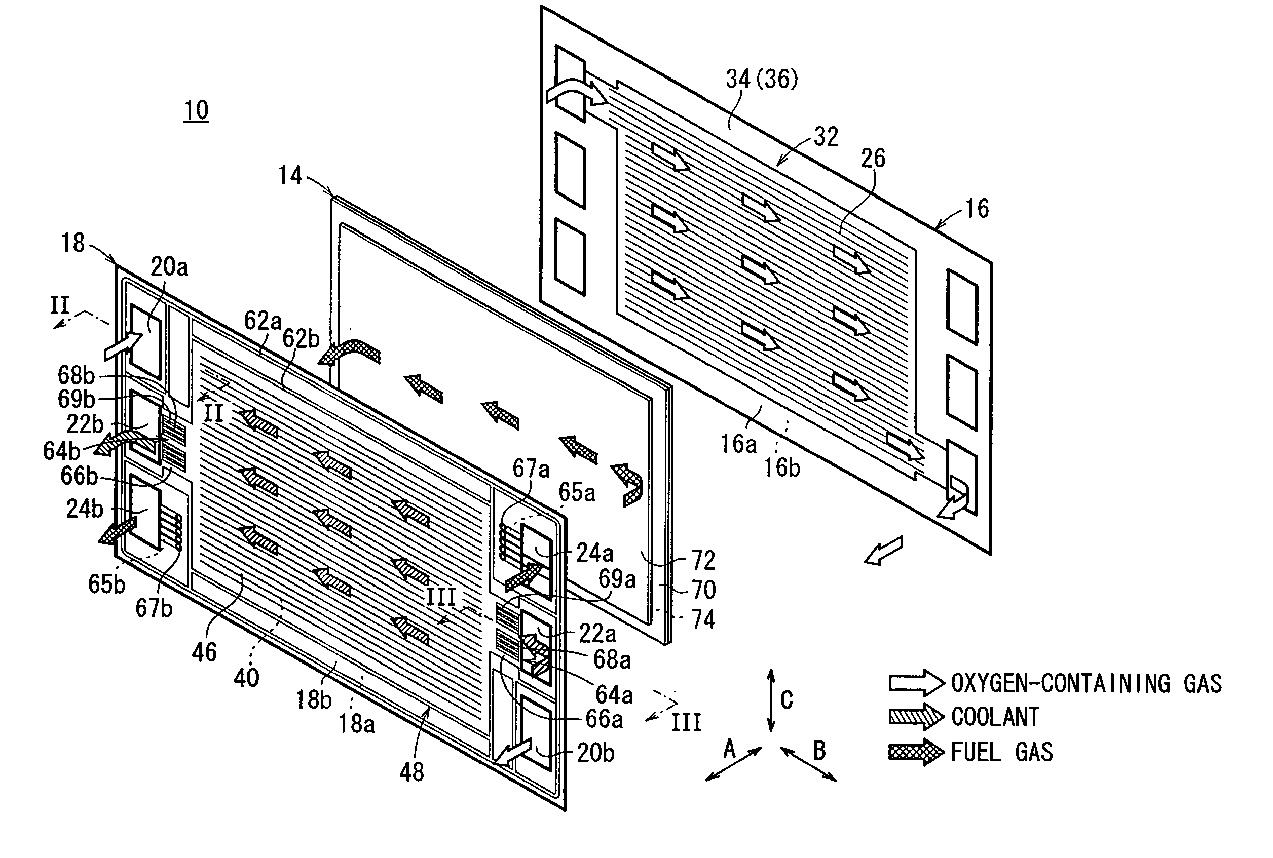
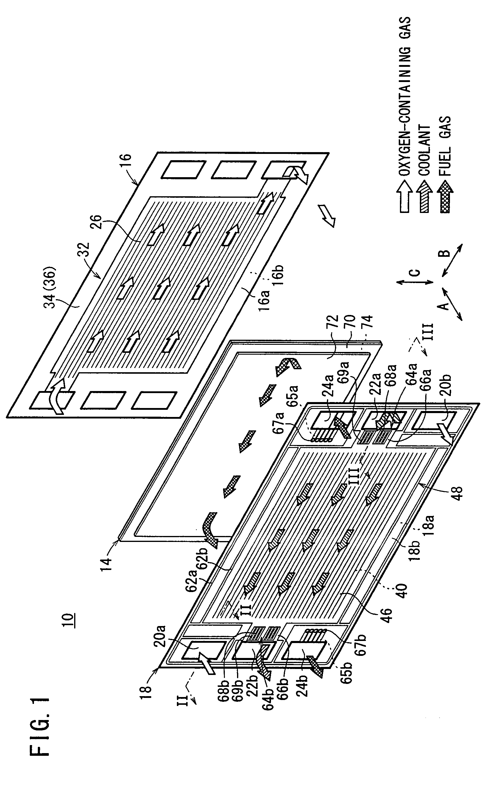
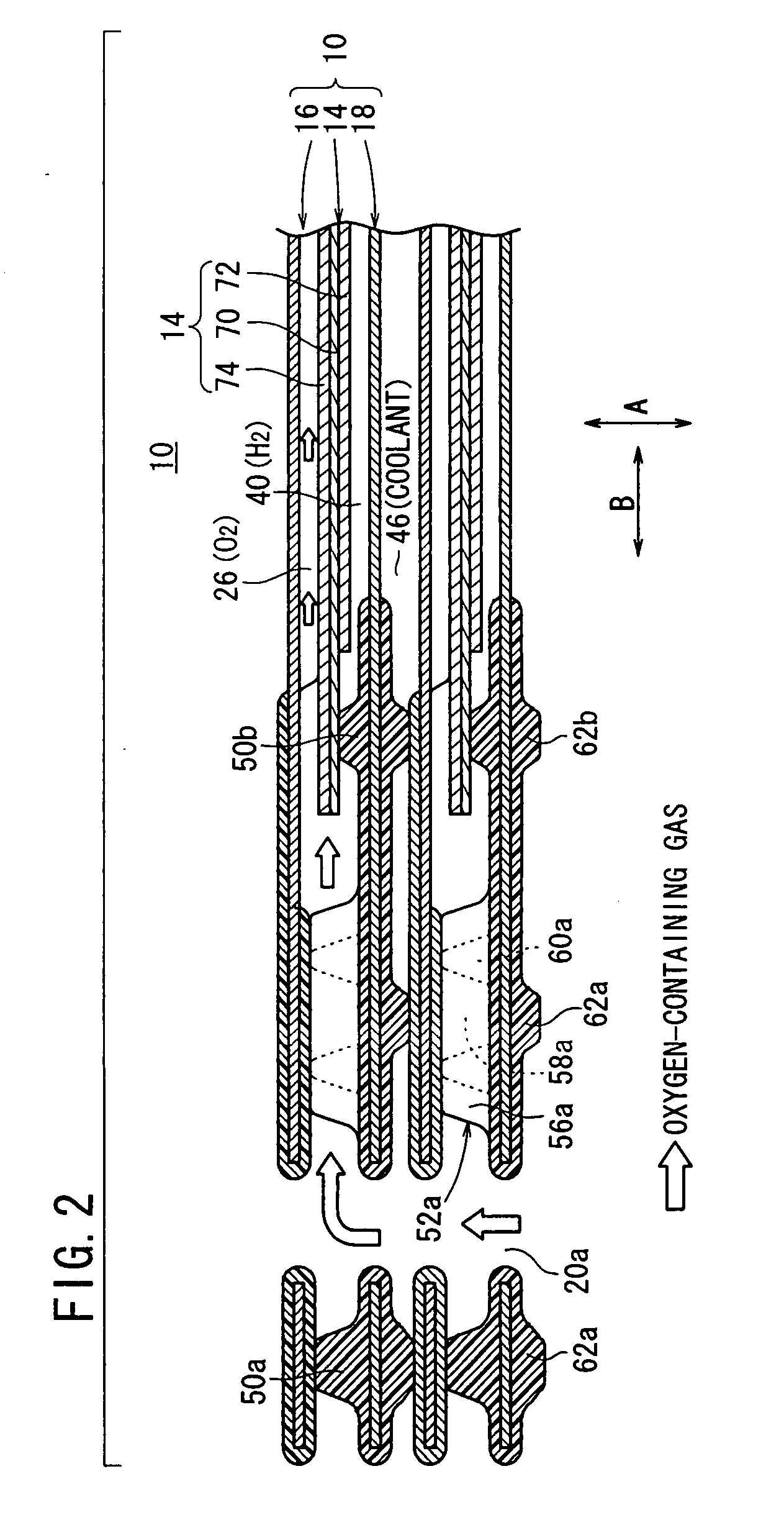
[0031]FIG. 1 is an exploded perspective view showing main components of a fuel cell 10 according to the present invention. FIG. 2 is a cross sectional view showing a fuel cell stack 12 formed by stacking a plurality of the fuel cells 10, taken along a line II-II in FIG. 1.
[0032]FIG. 3 is a cross sectional view showing the fuel cell stack 12, taken along a line III-III in FIG. 1.
[0033] As shown in FIG. 1, each of the fuel cells 10 includes a membrane electrode assembly (electrolyte electrode assembly) 14 and a first metal separator 16 and a second metal separator 18 sandwiching the membrane electrode assembly 14. For example, the first metal separator 16 and the second metal separator 18 are steel plates, stainless steel plates, aluminum plates, or plated steel plates.
[0034] At one end of the fuel cell 10 in a horizontal direction indicated by an arrow B, an oxygen-containing gas supply passage 20a for supplying an oxidant gas such as an oxygen-containing gas, a coolant discharge p...
third embodiment
[0073]FIG. 10 is a view showing one surface 18a of a second metal separator 90 of a fuel cell according to the present invention.
[0074] Rubber bridges (rubber wall members) 92a, 92b are provided near the oxygen-containing gas supply passage 20a and the oxygen-containing gas discharge passage 20b, respectively. In effect, the rubber bridges 92a, 92b are divided into three parts by a plurality of channels 56a, 56b. A plurality of grooves 94a, 94b are formed between the channels 56a, 56b. The grooves 94a, 94b are narrower than the channels 56a, 56b. Partitions 96a, 96b are provided in the rubber bridges 92a, 92b for closing the grooves 94a, 94b at one upstream end in the fluid flow direction to prevent the flow of the oxygen-containing gas (see FIGS. 10 and 11).
[0075] Though not shown, the rubber bridges 92a, 92b are provided on the surface 18b of the second metal separator 90 instead of the rubber bridges 64a, 64b.
fourth embodiment
[0076]FIG. 12 is a view showing one surface 18a of a second metal separator 100 of a fuel cell according to the present invention.
[0077] Rubber bridges (rubber wall members) 102a, 102 are formed on the surface 18a of the second metal separator 100 near the oxygen-containing gas supply passage 20a and the oxygen-containing gas discharge passage 20b, respectively. In effect, the bridges 102a, 102b are divided into three parts by a plurality of channels 56a, 56b. A plurality of grooves 104a, 104b are formed between the channels 56a, 56b. The grooves 104a, 104b are narrower than the channels 56a, 56b. A pair of partitions 106a, 106b are provided in the rubber bridges 102a, 102b. The partitions 106a 106b close the grooves 104a, 104b at both ends in the fluid flow direction to prevent the flow of the oxygen-containing gas (see FIGS. 12 and 13).
[0078] Though not shown, the rubber bridges 102a, 102b are provided on the surface 18b of the second metal separator 100 instead of the rubber bri...
PUM
| Property | Measurement | Unit |
|---|---|---|
| Flow rate | aaaaa | aaaaa |
Abstract
Description
Claims
Application Information