Exhaust heat recovering device

a heat recovery device and exhaust gas technology, applied in the direction of indirect heat exchangers, machines/engines, light and heating apparatus, etc., can solve the problems of no consideration particularly seen regarding the heat of the insulating part formed, waste heat of the exhaust gas will no longer be able to be transported to the condenser, etc., to achieve reliable heat transport

Inactive Publication Date: 2008-05-22
DENSO CORP
View PDF3 Cites 36 Cited by
  • Summary
  • Abstract
  • Description
  • Claims
  • Application Information

AI Technical Summary

Benefits of technology

[0005]The object of the present invention, in consideration of the above problem, is to provide a waste heat recovery system utilizing heat pip...

Problems solved by technology

However, in this waste heat recovery system, no consideration is particularly seen regarding the heat of the insulating part formed between the evaporator and condenser.
For example, if the insulating part is struck by cooling a...

Method used


Image

  • Exhaust heat recovering device
  • Exhaust heat recovering device
  • Exhaust heat recovering device

Examples


Embodiment Construction

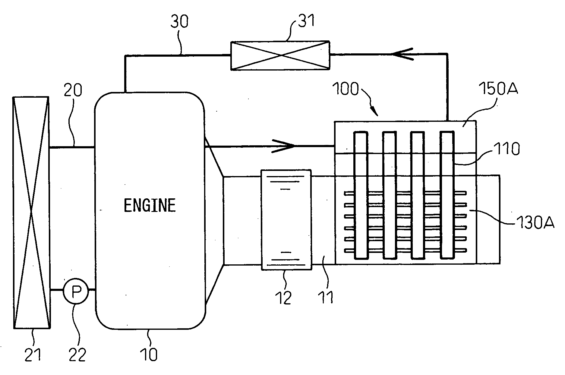
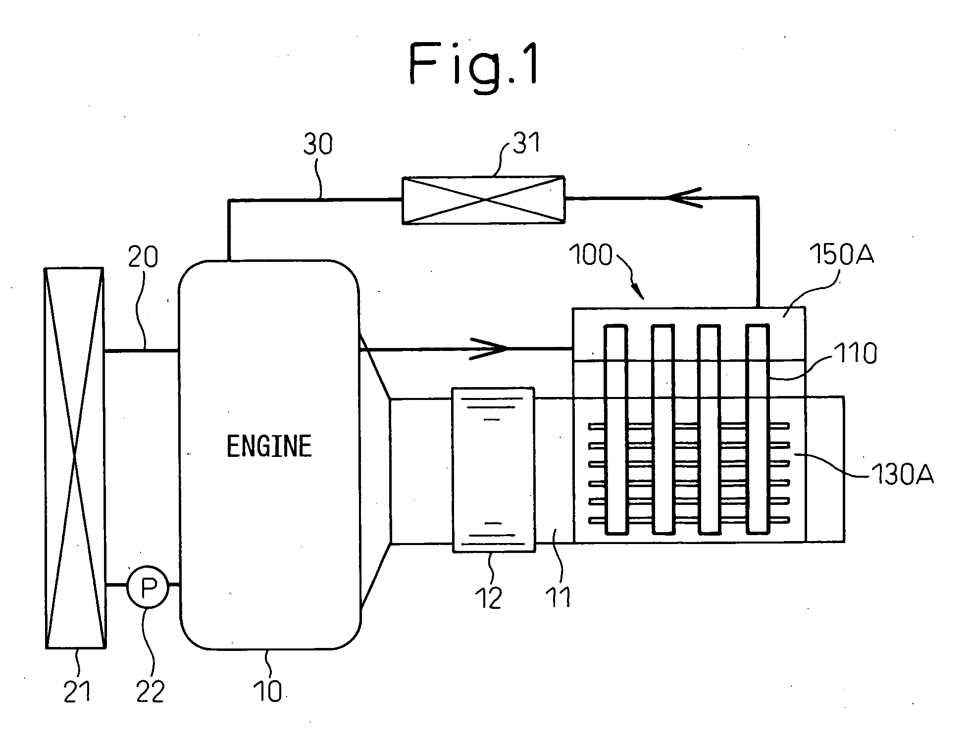
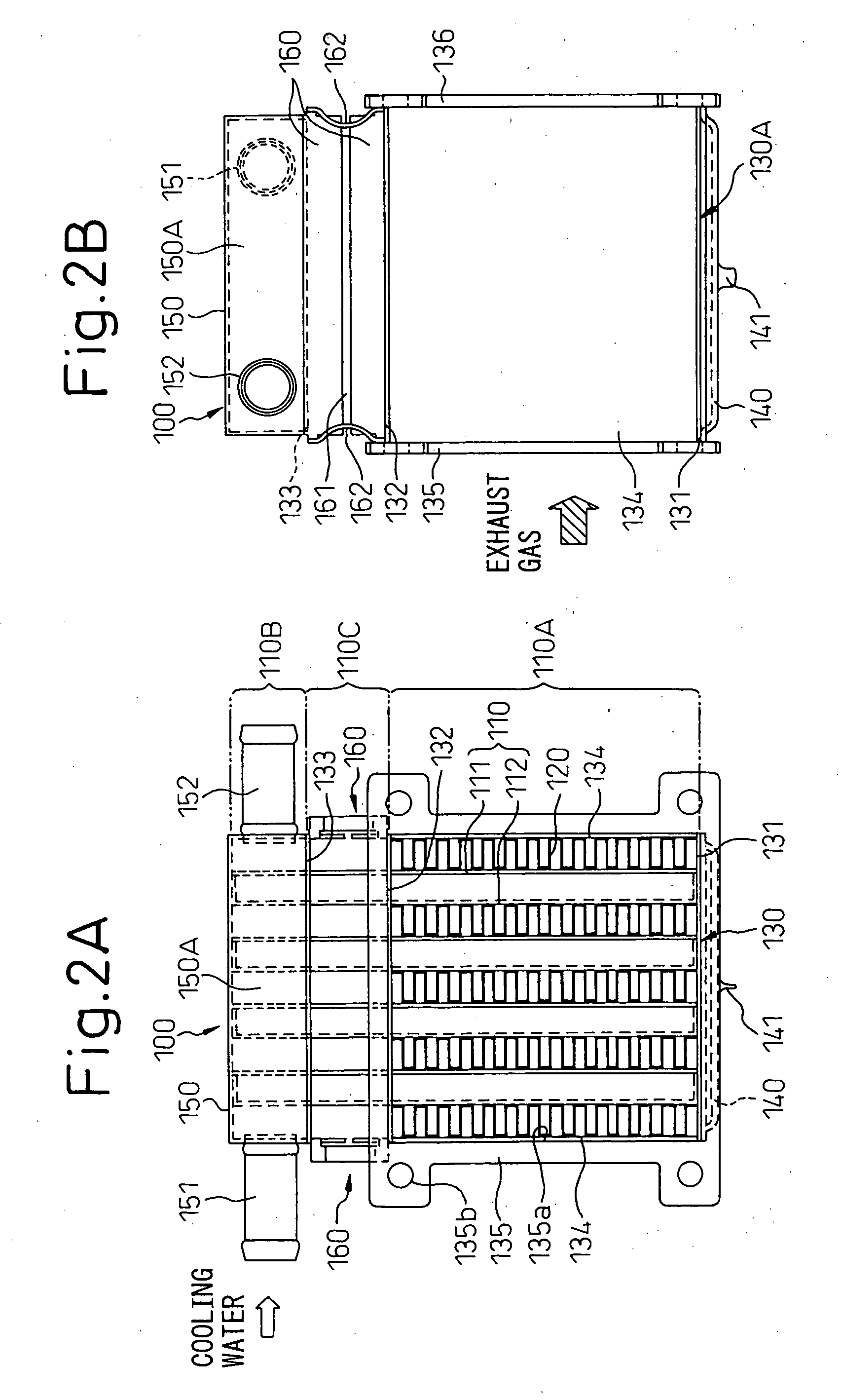
[0032]A first embodiment of the present invention is shown in FIG. 1 to FIG. 3. First, the specific configuration will be explained. A waste heat recovery system 100 of the present embodiment is applied to a vehicle (automobile) having an engine 10 as a drive source for running. In this connection, FIG. 1 is a schematic view showing the state of the waste heat recovery system 100 mounted in a vehicle, FIG. 2A is a front view showing the waste heat recovery system 100, FIG. 2B is a right side view of FIG. 2A, and FIG. 3 is a graph showing the amount of heat transferred to the engine cooling water by the waste heat recovery system 100.

[0033]As shown in FIG. 1, a vehicle engine 10 is a water-cooled internal combustion engine which has an exhaust pipe 11 from which exhaust gas is exhausted after fuel is burned. The exhaust pipe 11 is provided with a catalytic converter 12 for purifying the exhaust gas.

[0034]Further, the engine 10 has a radiator circuit 20 by which the engine 10 is coole...


PUM


Abstract

A waste heat recovery system having a heat pipe provided with a heat switch function limiting an amount of heat transported to a condenser in accordance with the increase in the amount of heating of the evaporator, having the evaporator arranged at an exhaust pipe for carrying exhaust gas of the internal combustion engine, and having the condenser arranged in a cooling water passage for carrying cooling water of the internal combustion engine and using the heat pipe to transport waste heat of exhaust gas to cooling water, characterized in that an insulating part formed between the evaporator and condenser is provided with a wall part for preventing heat transmission from an external fluid.

Description

TECHNICAL FIELD[0001]The present invention relates to a waste heat recovery system using heat pipes to recover waste heat of exhaust gas of an internal combustion engine and utilizing it for heating cooling water of the internal combustion engine, for example, is suitably used for a vehicle provided with an internal combustion engine.BACKGROUND ART[0002]As a conventional waste heat recovery system, for example, as shown in the reference (Wolf Dietrich Munzel, Daimler-Benz AG, “Heat Pipes for Recovery from Exhaust Gas of a Diesel Engine in a Passenger Car”, Proc. of International Heat Pipe Conference in Grenouble, France, 1987, pp. 740-743), one is known where the evaporator among the evaporator and condenser of the heat pump is placed in an engine exhaust pipe and the condenser is brought into heat contact with the engine cooling water. In this waste heat recovery system, waste heat of the exhaust gas is transported to the engine cooling water by the heat pipes, whereby the engine c...

Claims


Application Information

Patent Timeline
IPC IPC(8): F28F27/00
CPCF01N5/02F01P9/02F01P2060/16F02G5/04F28D15/0233F28D15/0275F28F2270/00F28F1/126F28F1/28F28F1/32Y02T10/16Y02T10/166F28D21/0003Y02T10/12
Inventor YAMANAKA, YASUTOSHIHAMADA, SHINICHIINOUE, SEIJIKOHARA, KIMIO
Owner DENSO CORP
Why Eureka
Try Eureka