Method for Running Tubulars in Wellbores

a wellbore and tubular technology, applied in the direction of directional drilling, wellbore/well accessories, sealing/packing, etc., can solve the problems of uneconomical oil and gas capture, inability to run the casing or liner into the well, and none of the methods to reduce the friction coefficient can reduce the coefficient to zero, so as to reduce the drag acting

Active Publication Date: 2008-05-22
EXXONMOBIL UPSTREAM RES CO
View PDF10 Cites 37 Cited by
  • Summary
  • Abstract
  • Description
  • Claims
  • Application Information

AI Technical Summary

Benefits of technology

[0014]In a first embodiment, a method for inserting a tubular into a wellbore is disclosed. The method comprises a) selecting an external tubular running fluid having a density, that reduces drag acting on a tubular to be run into at least one deviated portion of the wellbore, b) placing the external tubular-running fluid into at least a part of the deviated portion of the wellbore, c) running the tubular into the wellbore with a plug in the lower portion of the tubular that prevents the tubular running fluid from mixing with the fluid inside the tubular above the plug

Problems solved by technology

The use of ER wells typically results in less cost, and may result in capture of oil and gas that would otherwise be uneconomic.
However, for horizontal or high-angle wells, because of the drag created by axial friction between the pipe and the wellbore, it may be impossible to run the casing or liner into the well using current practice.
However, none of the methods to reduce the friction coefficient can reduce the coefficient to zero.
Thus, there is a limit on the length of casing or liner that can be run in high-angle wells using the friction reduction technology.
However, rotation is often limited by the torque capacity of the rig and / or the pipe connections.
Also, since there is always some axial component of the frictional force, rotation cannot completely eliminate the axial drag.
Thus, there is a limit on the length of casing or liner that can be run in a high-angle well using rotation.
The internal lightweight fluid reduces the effective weight per foot of the casing or liner and thereby reduces the normal force.
It is typically not possible to cause the casing or liner to become neutrally buoyant by simply reducing the density of the internal fluid or even running the string with a gas inside.
Therefore, there still typically exists a normal force between the casing and the wellbore when utilizing conventional technology since the casing or liner is not neutrally buoyant.
This normal force creates a limit to the length of pipe that can be run in a high-angle well even using conventional casing floatation.
Increasing the diameter of the casing or liner is often not feasible because the casing or liner has to fit through a previous casing string and into the borehole that has been drilled.
Increasing the diameter and / or decreasing the wall thickness may also cause problems with satisfying other design requirements related to the collapse and burst resistance of the pipe string.
The lightweight fluid reduces the effective weight per foot of the tubular in the high-angle part of the wellbore.
While these existing methods can be effective in installing tubulars in some high-angle wellbores, there are limitations associated with the current practice.
Specifically, since none of the current methods completely eliminate the axial friction force acting on the casing or liner in the high-angle portion of the well, there is a limit to the length of casing or liner that can be run into a high-angle well.
Another limitation of current practice is that the current casing floatation technique may increase the risk of collapsing the casing or liner.

Method used


Image

  • Method for Running Tubulars in Wellbores
  • Method for Running Tubulars in Wellbores
  • Method for Running Tubulars in Wellbores

Examples


Embodiment Construction

[0029]The present invention will be described in connection with its preferred embodiments. However, to the extent that the following description is specific to a particular embodiment or a particular use of the invention, this is intended to be illustrative only, and is not to be construed as limiting the scope of the invention. On the contrary, it is intended to cover all alternatives, modifications, and equivalents that are included within the spirit and scope of the invention, as defined by the appended claims.

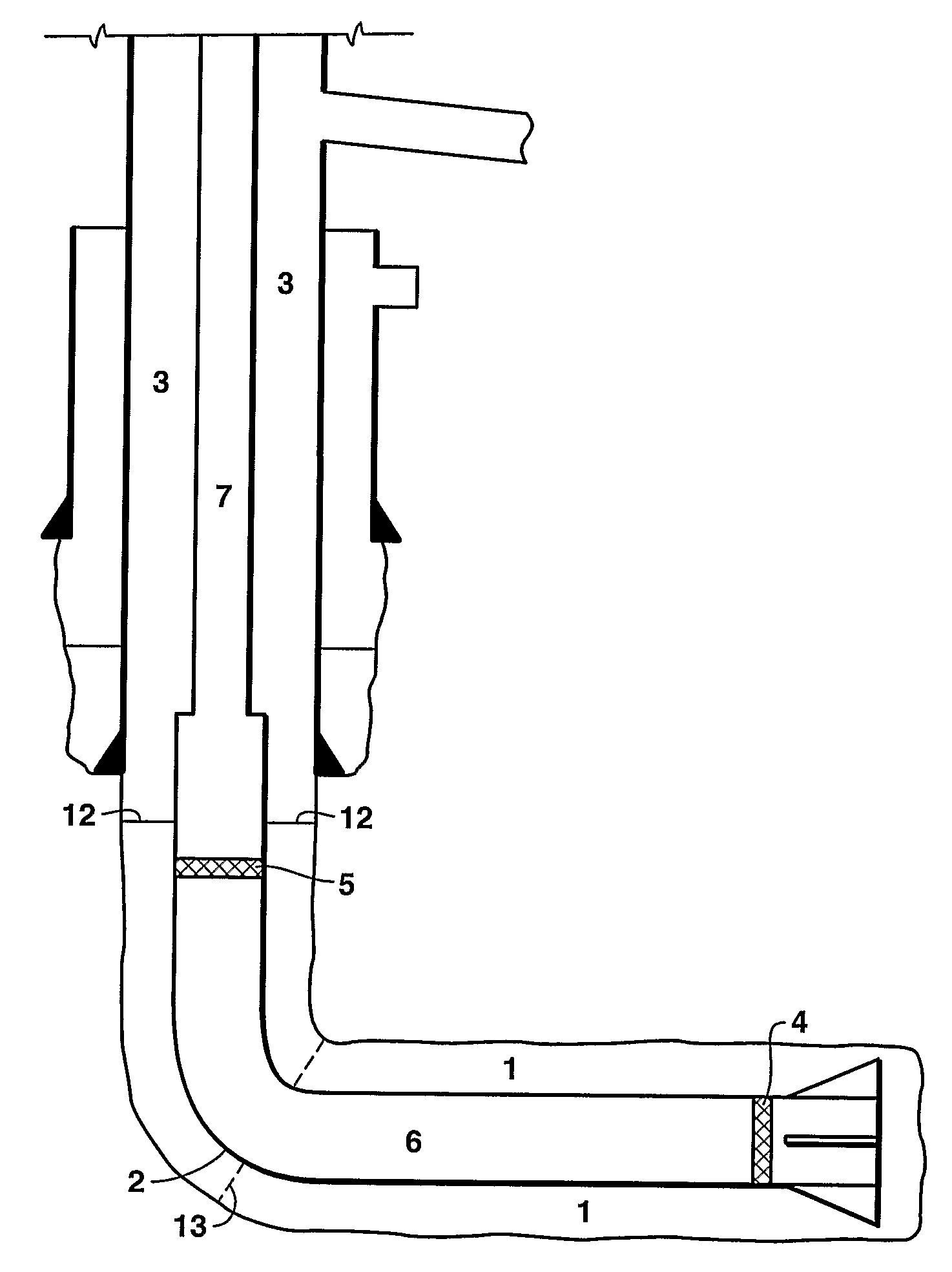
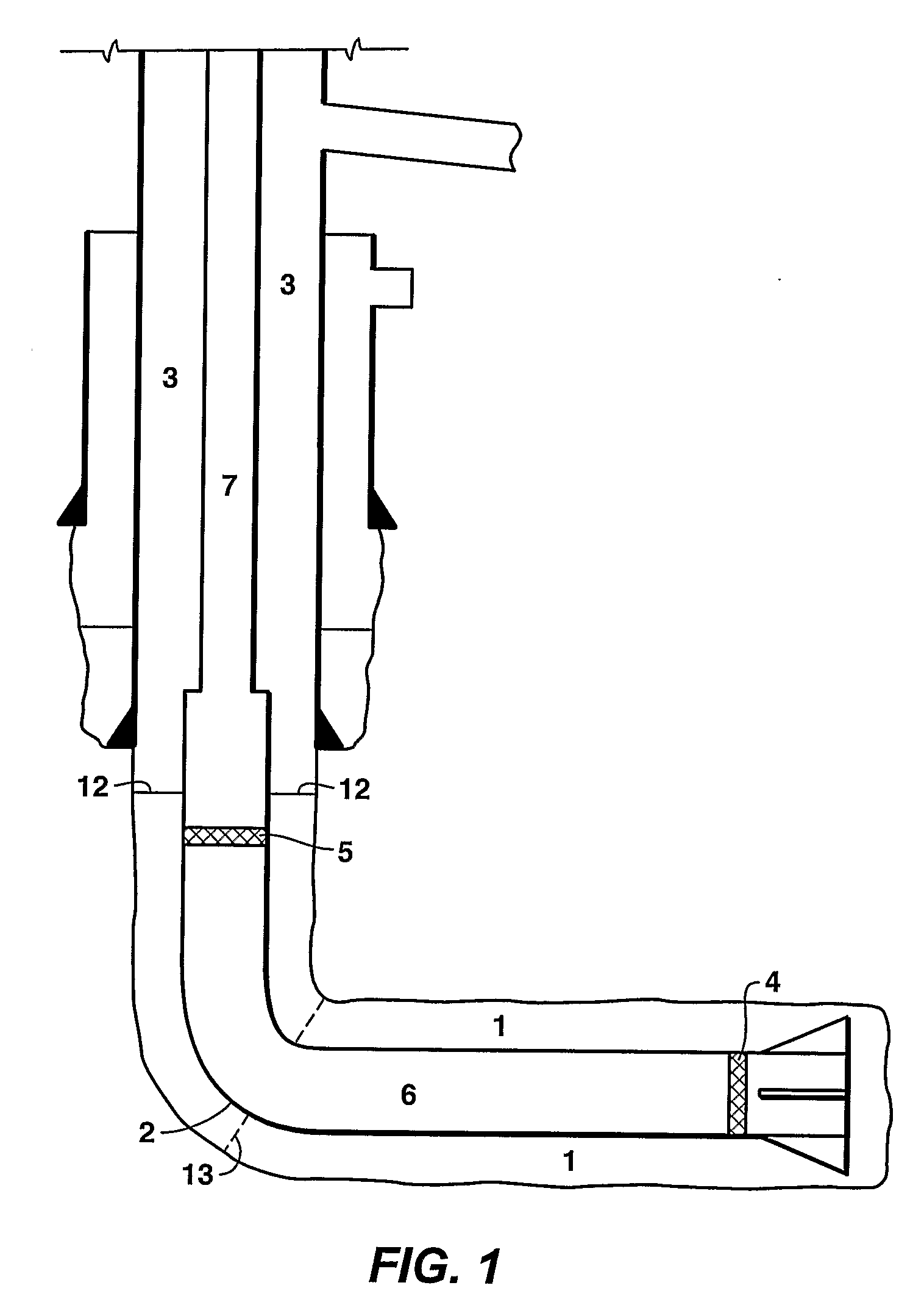
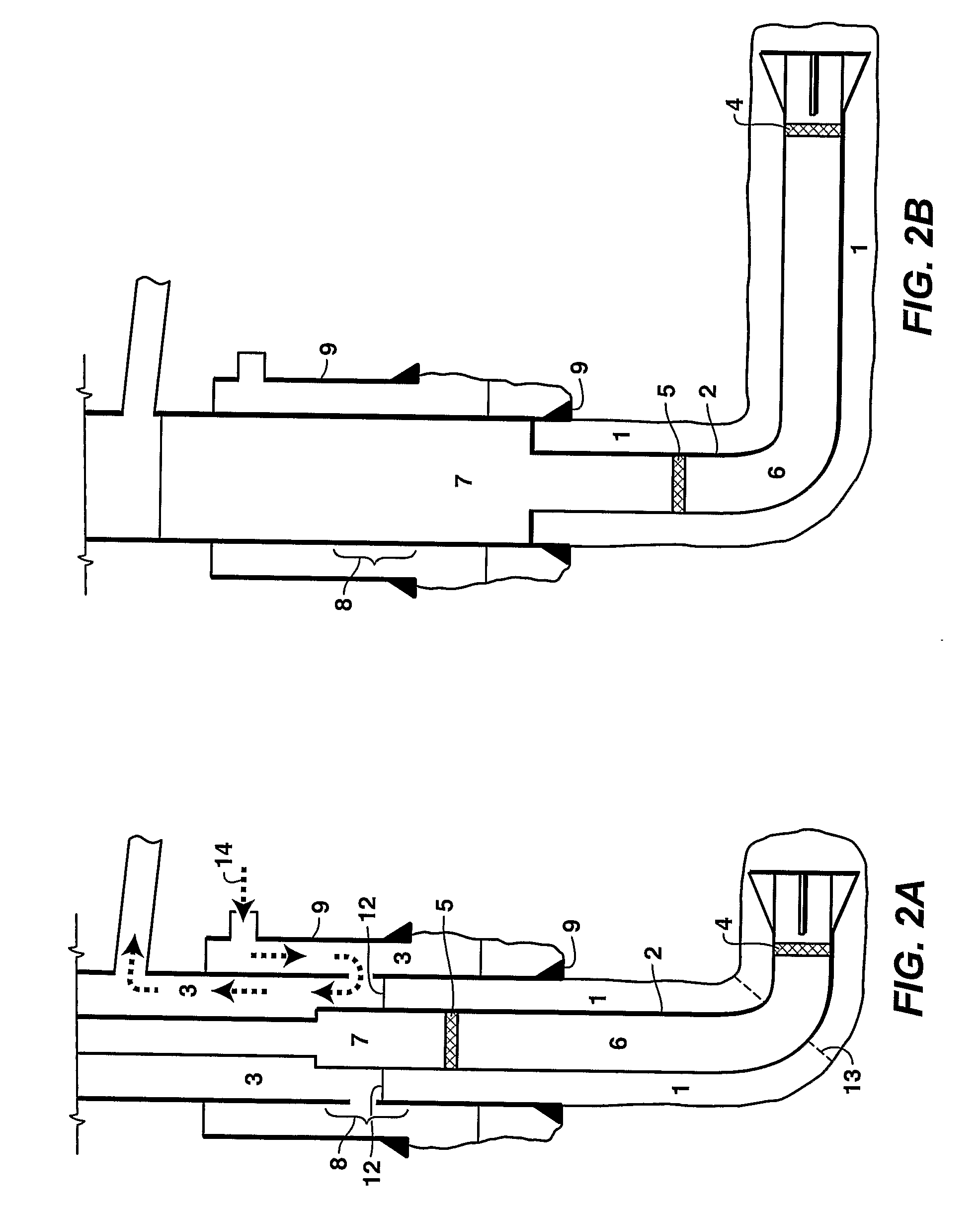
[0030]This invention provides a method for buoyancy-aided insertion of a tubular into a long or high-angle wellbore by controlling the density of the external (annular) fluid. In one embodiment, the fluid density is controlled such that the tubular or conduit, including coiled tubing, is essentially neutrally buoyant in the high-angle portions of the wellbore and negatively buoyant in the low-angle portions of the wellbore. The process is further facilitated by using conve...


PUM


Abstract

Methods for installing tubulars (for example, conduits, casing or liners) into a highly deviated wellbore are disclosed. In a first embodiment, the method comprises a) drilling the well to the planned total depth of the interval, b) placing a first fluid into the wellbore below a prescribed measured depth in the high-angle portion of the wellbore, said first fluid having a density that causes the portion of the tubular that extends into the first fluid to become substantially neutrally buoyant, c) placing a second fluid into the wellbore above the prescribed measured depth, said second fluid having a density less than said first fluid, d) plugging the distal portion of the tubular with a lower plug (or check valve) and an upper plug, e) as the tubular is run into the wellbore, placing a lightweight fluid into the plugged section of tubular and a heavy fluid above the plugged section of tubular, and f) running the tubular into the wellbore to the planned total depth.

Description

[0001]This application claims the benefit of U.S. Provisional Application No. 60 / 664,110, which was filed on Mar. 22, 2005.FIELD OF THE INVENTION[0002]This invention relates generally to the field of well drilling and, in particular, to installation of casing or liners into oil and gas wellbores. Specifically, the invention is a method that enables running well tubulars into long and highly deviated wellbores.BACKGROUND OF THE INVENTION[0003]In developing oil and gas resources, it is often desirable to drill long, extended-reach (“ER”) wells from a fixed drilling center such as a platform, pad, or subsea template. The ER wells allow distal parts of a field or distal reservoirs to be developed without having to construct a new wellbore or move the drilling center. The use of ER wells typically results in less cost, and may result in capture of oil and gas that would otherwise be uneconomic. The ER wells also have a number of other advantages, including less environmental impact and t...

Claims


Application Information

Patent Timeline
Patent Type & Authority Applications(United States)
IPC IPC(8): E21B19/16
CPCE21B43/10E21B34/06
Inventor KELLER, STUART R.MONTGOMERY, JOHN K.SPIECKER, PAUL M.DALE, BRUCE A.
Owner EXXONMOBIL UPSTREAM RES CO
Why Eureka
Try Eureka