
High-Pressure Discharge Lamp Lighting Device

a technology of high-pressure discharge and lighting device, which is applied in the direction of cathode-ray/electron beam tube circuit elements, electric variable regulation, instruments, etc., can solve the problems of insufficient life of projectors used mainly in school classrooms and conference rooms, insufficient 2000 to 3000 hour life of projectors, and insufficient life of previous lamps. achieve long-term stability, maintain stability, and maintain stability

Active Publication Date: 2008-05-22
PANASONIC CORP
View PDF11 Cites 27 Cited by
  • Summary
  • Abstract
  • Description
  • Claims
  • Application Information

AI Technical Summary

Benefits of technology

[0011]Moreover, there is the issue of stability for the subtly varying properties such as color reproduction and brightness of the displayed image. As previously indicated, in displays such as home theater systems capable of realizing television pictures and large screens, long-term stability is required. Analysis of this problem reveals that the key to maintaining stability is to maintain the form of the electrode tips. The central point of emission from the light source is located in the lamp electrode gap. The brightness and color reproduction of the projector are influenced by the size of the central point of emission, and the location of the same point is important because of its relationship with the optical axis of the optical system. As a consequence, if the form of the electrodes is maintained, it is possible to maintain stability of properties such as the subtle variations in image color reproduction and brightness.
[0012]It is an object of the present invention to provide a high-pressure discharge lamp lighting device, a high-pressure discharge lamp apparatus, a projection-type image display apparatus, and a high-pressure discharge lamp lighting method all of which are capable of improving a life that is determined as the period before a certain drop in intensity, and of maintaining over the life stability with respect to properties such as the subtle variation of color reproduction, brightness and the like.
[0039]According to the present invention, it is possible to provide a high-pressure discharge lamp lighting device, a high-pressure lamp device, a projection type image display device and a high-pressure discharge lamp lighting method all of which are capable of improving a life that is determined as the period before a certain drop in luminance, and of maintaining over the life the stability of properties such as the subtle variation of color reproduction and brightness.

Problems solved by technology

However, in recent years a new problem has arisen as a result of the range of applications for liquid crystal projectors displays expanding to include home theater systems capable of wide screen display an of displaying television pictures.
Hence, it can be assumed that a period of use is incomparably longer than that of previous technologies.
Consequently, the 2000 to 3000 hour life of the projectors that were used mainly in the school classroom and conference rooms is insufficient, and a life several times that of previous lamps is required.
However, application of these previously available lighting methods in devices such as home theater systems capable of realizing television screens and large screens did not enable a long life (6000 hours, for instance) and stable color reproduction and brightness to be obtained.
In the lamp lighting method of previous lamps this was controlled by detecting the discharge voltage and varying the frequency of the supplied alternating current, but the variation of the discharge voltage in this process is slow, and such a control method does not work effectively.
For reasons such as this, in the period spanning between 2000 and 3000 hours after lamp driving was begun, it was difficult to perfectly maintain the initial form of the electrodes by means of the control method for keeping the same driving frequency condition.
Moreover, there is the issue of stability for the subtly varying properties such as color reproduction and brightness of the displayed image.

Method used


Image

  • High-Pressure Discharge Lamp Lighting Device
  • High-Pressure Discharge Lamp Lighting Device
  • High-Pressure Discharge Lamp Lighting Device

Examples


first embodiment

[0061]An embodiment of the invention is described in detail below with reference to the drawings.

[0062]1. Structure of a high-pressure mercury lamp

[0063]As one example of a high-pressure discharge lamp, the structure of a high-pressure mercury lamp is described below.

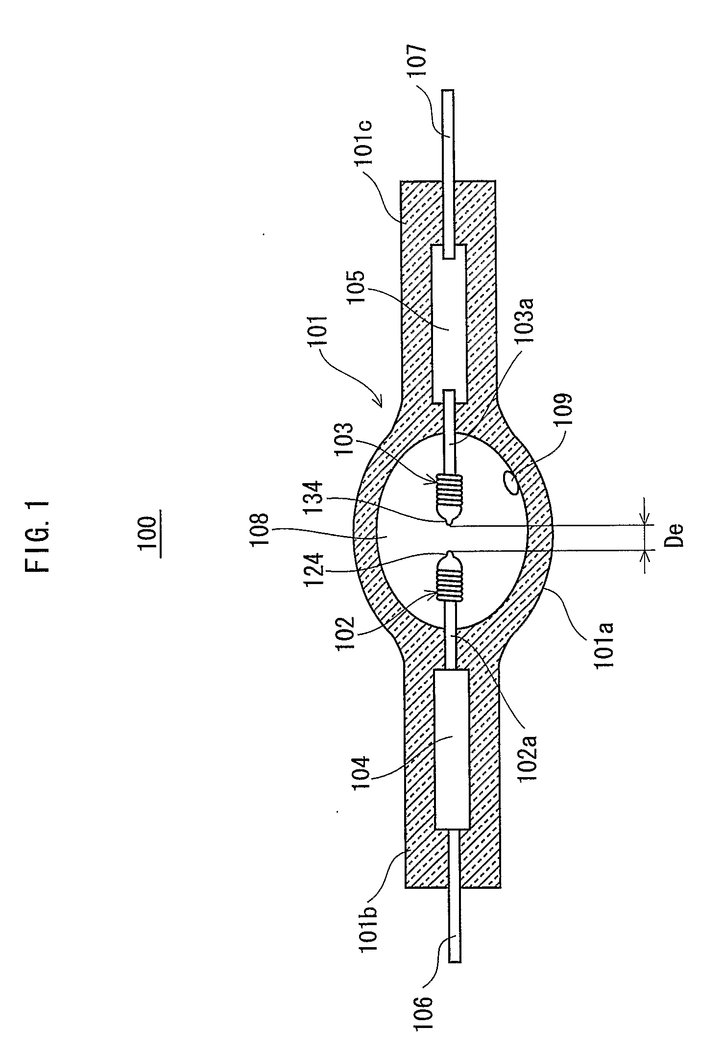
[0064]FIG. 1 shows a general structure of a high-pressure mercury lamp 100 with a 130 W power rating (hereinafter referred to as “the lamp”).

[0065]As shown in FIG. 1, an arc tube 101 has an external casing manufactured from quartz glass, and includes an emission section 101a and seal sections 101b and 101c that are provided at the ends of the emission section 101.

[0066]The emission section 101i a is of a substantially spheroidal form, and encloses, in an internal discharge space (a light emission space) 108 thereof, mercury 109 that is a light emitting material, an inert gas such as argon (Ar), Krypton (Kr), Xenon (Xe), or the like, and for aiding start-up, a halogen material such as Iodine (I), Bromide (Br), or the li...


PUM


Abstract

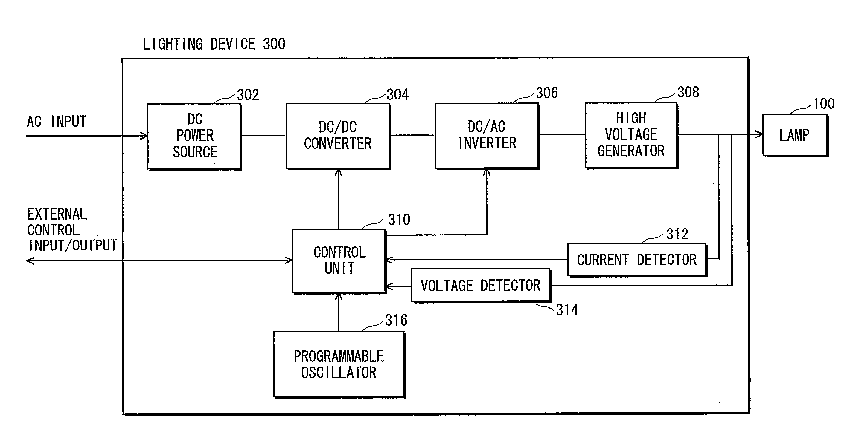
The high-pressure discharge lamp lighting device of the invention includes a lighting circuit for supplying an alternating current to a high-pressure discharge lamp to cause lighting, the high-pressure discharge lamp having an arc tube in which a halogen material is enclosed and a pair of electrodes is disposed, and each electrode having a protuberance at a tip thereof. A frequency of the alternating current varies without dependency on operating data that varies as a lighting time of the high-pressure discharge lamp elapses.

Description

TECHNICAL FIELD [0001]The present invention relates to a high-pressure discharge lamp lighting device, a high-pressure discharge lamp apparatus, a projector-type image display device, and a high-pressure discharge lamp lighting method, and relates in particular to a high-pressure discharge lamp lighting device that causes current to flow in a high-pressure discharge lamp causing lighting.BACKGROUND ART [0002]Among high-pressure discharge lamps, the high-pressure mercury lamp, which is used as a light source in projector-type image display devices such as liquid crystal projectors and the like, has in recent years been attracting particular attention (see Japanese Laid-open Patent Application No. H4-303592).[0003]Generally, the high-pressure mercury lamp has a pair of opposing electrodes disposed inside an arc tube enclosing a halogen material, an inert gas, and mercury. A high-pressure discharge lamp lighting device applies a predetermined high voltage pulse to the high-pressure dis...

Claims


Application Information

Patent Timeline
IPC IPC(8): H05B41/24
CPCY02B20/208H05B41/2928Y02B20/00H05B41/24H05B41/282H05B41/292
Inventor OZASA, MINORUONO, SYUNSUKEIKEDA, MASARUYAMAMOTO, MASAHIRO
Owner PANASONIC CORP
Learn More