
Printed wiring board manufacturing apparatus, printed wiring board, method for manufacturing printed wiring board, and electronic device

a printing method and wiring board technology, applied in the direction of soldering auxilary devices, glue vessels, circuit masks, etc., can solve the problems of reduced internal space, complicated shapes, etc., and achieves the effect of easy manufacturing of printed wiring boards, reduced size of electronic devices, and high mounting density

Inactive Publication Date: 2008-05-22
SHARP KK
View PDF0 Cites 47 Cited by
  • Summary
  • Abstract
  • Description
  • Claims
  • Application Information

AI Technical Summary

Benefits of technology

[0019]The present invention was made in view of such circumstances, and it is an object thereof to provide a printed wiring board manufacturing apparatus that easily manufactures a printed wiring board apparatus having a curved shape by applying a processing cylinder that holds a printed wiring board material in a printed wiring board manufacturing apparatus that manufactures a printed wiring board by performing processing on a printed wiring board material subjected to processing.
[0020]It is another object of the present invention to provide, by curving an insulating substrate of a printed wiring board, in which a wiring pattern including a component mounting land portion has been formed, in an area where the component mounting land portion has been curved, a printed wiring board in which the component mounting area is curved, and can thus be mounted and disposed in a small space, so that the printed wiring board is highly adaptable to an electronic device.
[0021]It is another object of the invention to provide, by performing processing on a printed wiring board using a processing cylinder in a printed wiring board manufacturing method in which printed wiring board material with which a printed wiring board is formed is layered, and processing is performed on the printed wiring board material to form a printed wiring board, a printed wiring board manufacturing method with which it is possible to easily manufacture a printed wiring board in which the component mounting area is curved, so the printed wiring board can be mounted and disposed in a small space, and thus the printed wiring board is highly adaptable to an electronic device.

Problems solved by technology

On the other hand, reduced size of electronic devices is accompanied by reduced internal space in a case that houses an electronic circuit (a printed wiring board), and more complicated shapes.
That is, with a conventional printed wiring board having a simple, flat shape, housing and interconnection of necessary electronic circuits may be difficult.
In an ordinary electronic device, when a conventional flexible printed wiring board or rigid-flex printed wiring board is used, it is possible for the flexible printed wiring board to be suitably compatible in such a case, but in the context of recent reductions in the size of electronic components, or requirements of design or the like, there are circumstances in which conventional compatibility cannot adequately satisfy the needs of an electronic device.
Accordingly, there is the problem that it is difficult to increase the mounting density of components because the maximum size of the printed wiring board 510 is limited by the diameter, and so the surface area of the printed wiring board 510 itself is also small.
Also, there is the problem that because the position where the printed wiring board 510 is disposed is limited, space efficiency is very poor, so it is difficult to reduce the size of the electronic device 500.
It is conceivable that using the printed wiring board in a state bent along the inner wall face of the case 501 by adopting a flexible printed wiring board as the printed wiring board 510 is desirable, but in actuality, the flexible printed wiring board itself is manufactured with a flat shape, and so there are risks that a break will occur and that layers will peel away from each other, if the printed wiring board bends in the area of a through-hole, a land portion for mounting a component, or the like.
As a result, there is the problem that curving of the printed wiring board in a shape that follows the case 501 has not been realized.
Although technology for bending a flexible printed wiring board has been proposed, but the portion that is bent is limited to simply a portion where a lead wire has been formed, and in reality the bend in the area of a through-hole, a land portion for mounting a component, or the like is not intended (for example, see JP 2000-40865A).
However, because it is necessary to form the hard portions 520a and the flexible portions 520b in the rigid-flex printed wiring board, there is the problem that the structure of the printed wiring board is complicated and so manufacturing cost increases.
There are also other problems, such as that components can only be mounted to the hard portions 520a, and so in actuality it is difficult to increase the surface area that can be used for mounting components.
Although technology applying a three-dimensional molded substrate appears to be ideal, many problems occur.
For example, injection molding dies are expensive, and formation of a solid molding substrate and formation of a wiring pattern are labor-intensive.
At the same time, there are many limitations arising from the applied materials and the manufacturing method, so there is the problem that it is difficult to realize high density, high precision, and high reliability in the manner of an ordinary printed wiring board.
Also, ordinarily, in the manufacturing facilities of printed wiring boards, there are many manufacturing apparatuses such as etching apparatuses and plating apparatuses, and in particular, there is the problem that these manufacturing apparatuses are long, with a length spanning tens of meters, and so factory floor area is large.

Method used


Image

  • Printed wiring board manufacturing apparatus, printed wiring board, method for manufacturing printed wiring board, and electronic device
  • Printed wiring board manufacturing apparatus, printed wiring board, method for manufacturing printed wiring board, and electronic device
  • Printed wiring board manufacturing apparatus, printed wiring board, method for manufacturing printed wiring board, and electronic device

Examples


embodiment 1

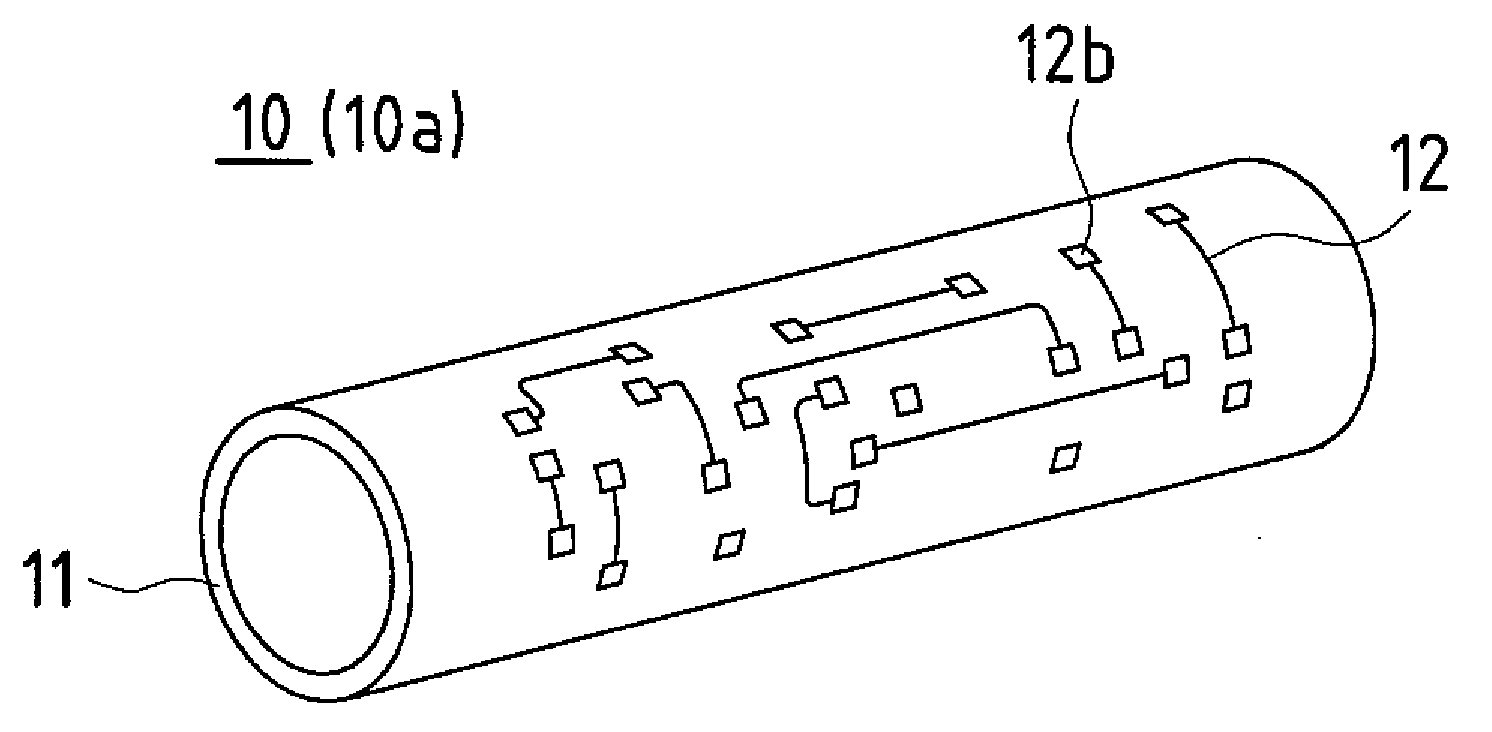
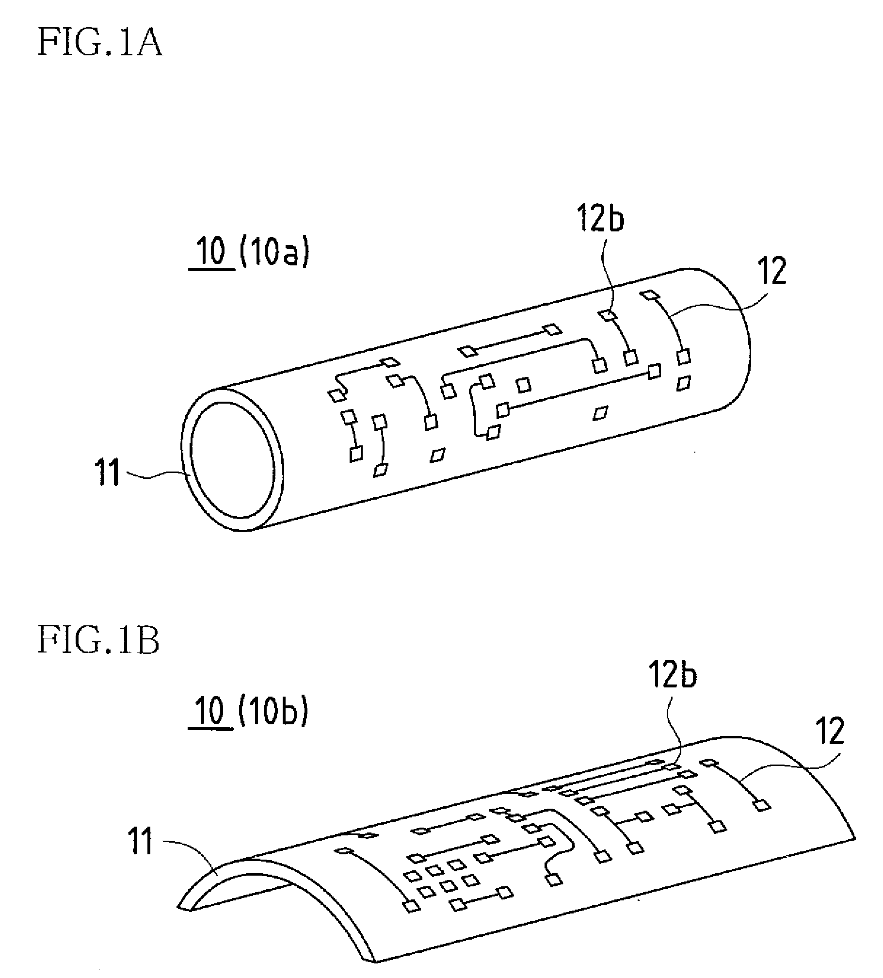
[0172]FIGS. 1A and 1B are perspective views that schematically show a printed wiring board according to Embodiment 1 of the present invention. FIG. 1A shows a case in which that printed wiring board is a cylindrical insulating substrate (printed wiring board), and FIG. 1B shows a case in which that printed wiring board is a curved arc-like insulating substrate (printed wiring board).

[0173]A printed wiring board 10 according to Embodiment 1 is provided with a curved insulting substrate 11 serving as a wiring substrate, and a wiring pattern 12 provided by a conductor layer formed on the insulating substrate 11. The wiring pattern 12 has a component mounting land portion 12b in a curved area of the insulating substrate 11.

[0174]More specifically, the printed wiring board 10 according to Embodiment 1 is a printed wiring board with the wiring pattern 12 having the component mounting land portion 12b formed in the insulating substrate 11, and the insulating substrate 11 is curved in the a...

embodiment 2

[0179]Next is a description of a printed wiring board manufacturing apparatus and printed wiring board manufacturing method used to form the printed wiring board 10 according to Embodiment 1, with reference to FIGS. 2 to 17D.

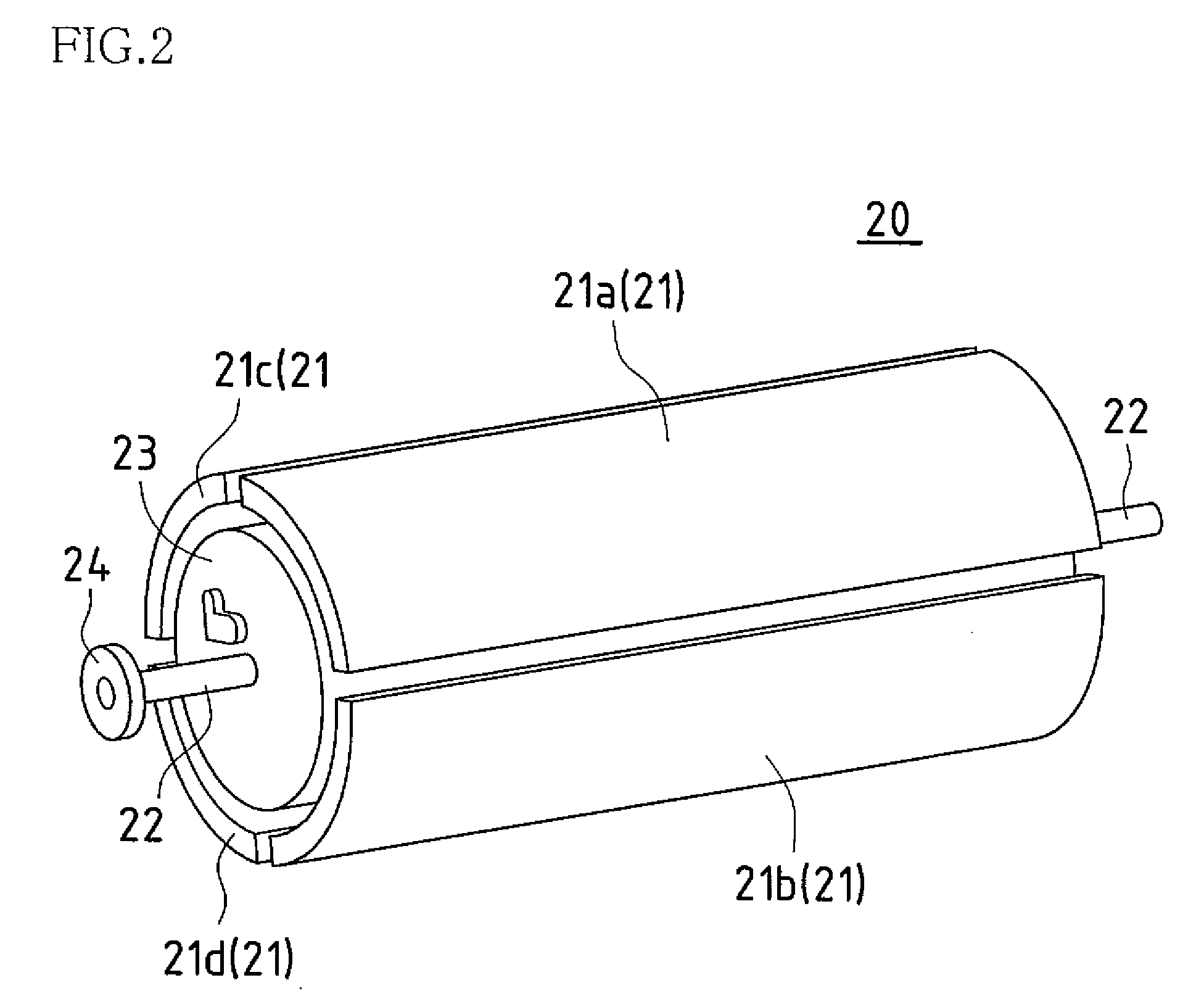
[0180]FIG. 2 is a perspective view that shows the general configuration of a drum unit serving as a constituent element of the printed wiring board manufacturing apparatus according to Embodiment 2 of the present invention.

[0181]A drum unit 20 serving as a constituent element of the printed wiring board manufacturing apparatus is provided with a processing cylinder 21, a rotational shaft 22, and a drive linking portion 24. The processing cylinder 21 constitutes a cylindrical outer circumference so as to function as a jig that holds a processing subject (printed wiring board material MAT that forms the printed wiring board 10; see FIGS. 4A, 4B, and 5; also includes a photosensitive resist or the like that, during processing, is layered, applied, and finally remov...

embodiment 3

[0351]In Embodiment 2, a case was disclosed in which a component mounting land portion where an electronic component is mounted is disposed on the outer circumference side of a cylindrical printed wiring board 10, but in the present embodiment, the component mounting land portion is disposed on the inner circumferential face (face opposite to that in Embodiment 2).

[0352]FIGS. 18, 19A and 19B are cross-sectional views that show the cross-sectional state of a printed wiring board formed by a printed wiring board manufacturing apparatus (printed wiring board manufacturing method) according to Embodiment 3 of the present invention.

[0353]The processing units and processing procedure applied in the present embodiment are basically the same as in Embodiment 2, and so in the present embodiment, mainly the processing procedure for layering is described using a cross-section of the printed wiring board 10. Other aspects of the configuration are the same as in Embodiments 1 and 2, so they are ...


PUM

PropertyMeasurementUnit
thicknessaaaaaaaaaa
thicknessaaaaaaaaaa
thicknessaaaaaaaaaa

Abstract

According to an embodiment of the present invention, a printed wiring board manufacturing apparatus being provided with a drum unit having a processing cylinder that holds the printed wiring board material and comprises a cylinder outer circumference and a processing unit that performs processing on the printed wiring board material held by the processing cylinder.

Description

BACKGROUND OF THE INVENTION[0001]This application claims priority under 35 U.S.C. § 119(a) on Japanese Patent Application No. 2006-313331 filed in Japan on Nov. 20, 2006, the entire contents of which are hereby incorporated by reference.[0002]The present invention relates to a printed wiring board manufacturing apparatus that manufactures a printed wiring board having a curved insulating substrate using a cylindrical body for processing having a cylindrical outer circumference, a printed wiring board having a curved insulating substrate, a method for manufacturing a printed wiring board having a curved insulating substrate, and an electronic device in which a printed wiring board having a curved insulating substrate is mounted.[0003]A printed wiring board used in an electronic device is ordinarily flat. This is because most electronic devices are box-shaped, and so it is advantageous in terms of space that the shape of a printed wiring board mounted inside an electronic device is fl...

Claims


Application Information

Patent Timeline
Patent Type & Authority Applications(United States)
IPC IPC(8): B32B3/02B32B37/02
CPCB32B37/0046Y10T428/13B32B38/145B32B2037/109B32B2037/243B32B2309/68B32B2310/0843B32B2457/08H05K1/0393H05K3/0052H05K3/0082H05K3/064H05K3/125H05K3/187H05K3/241H05K3/4652H05K2201/09018H05K2203/013H05K2203/0134H05K2203/0165H05K2203/0285H05K2203/095H05K2203/107H05K2203/1105B32B38/0004
Inventor UENO, YUKIHIRO
Owner SHARP KK
Learn More