

Direct-current motor and manufacturing method for the direct-current motor
a manufacturing method and technology of a direct-current motor, applied in the direction of manufacturing stator/rotor bodies, synchronous machines with rotating armatures, stationary magnets, etc., can solve the problems of increased vibration, difficult to suppress this vibration, and increased bearing size, so as to achieve the effect of suppressing the vibration of the rotor
- Summary
- Abstract
- Description
- Claims
- Application Information
AI Technical Summary
Benefits of technology
Problems solved by technology
Method used
Image

Examples
first embodiment
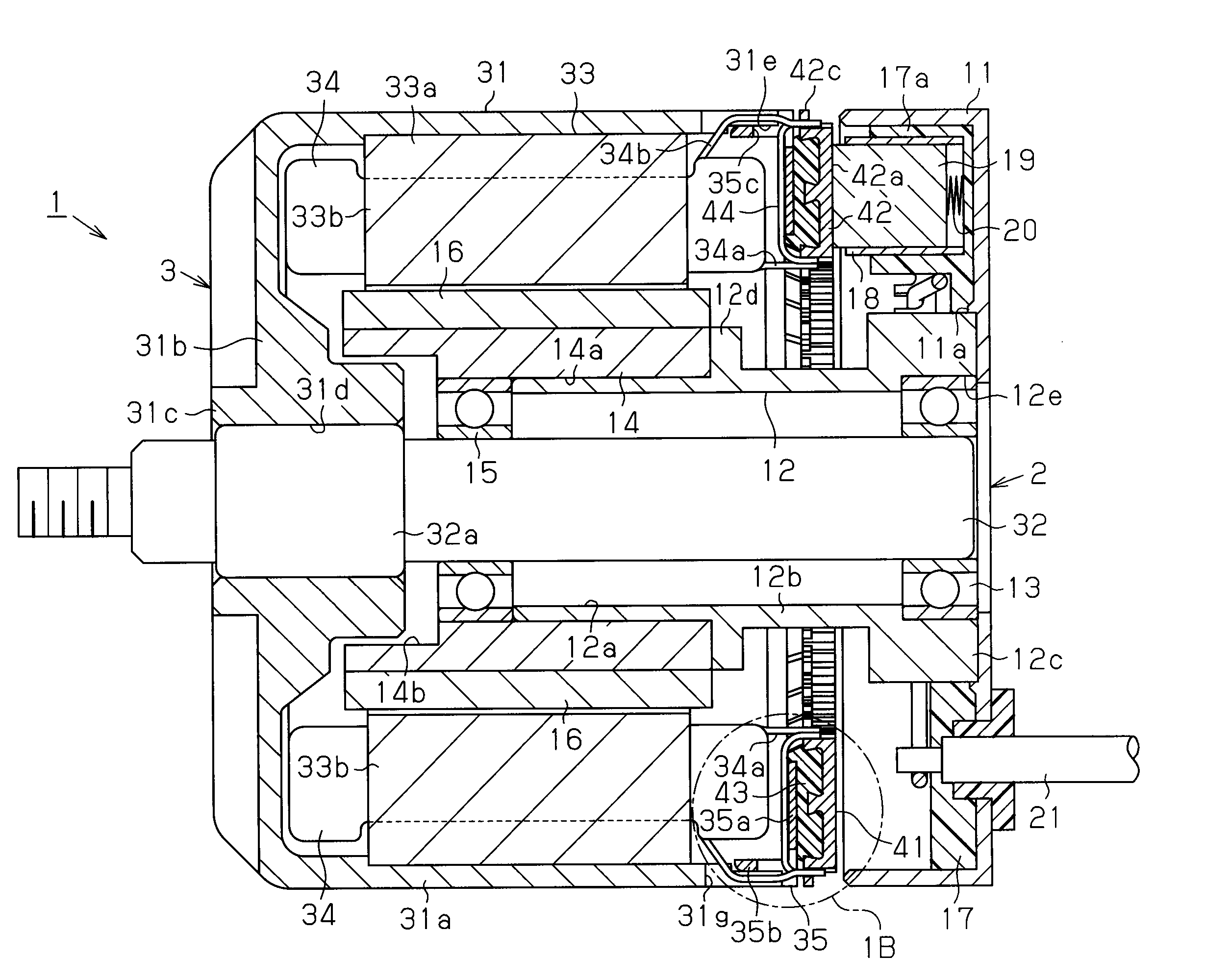
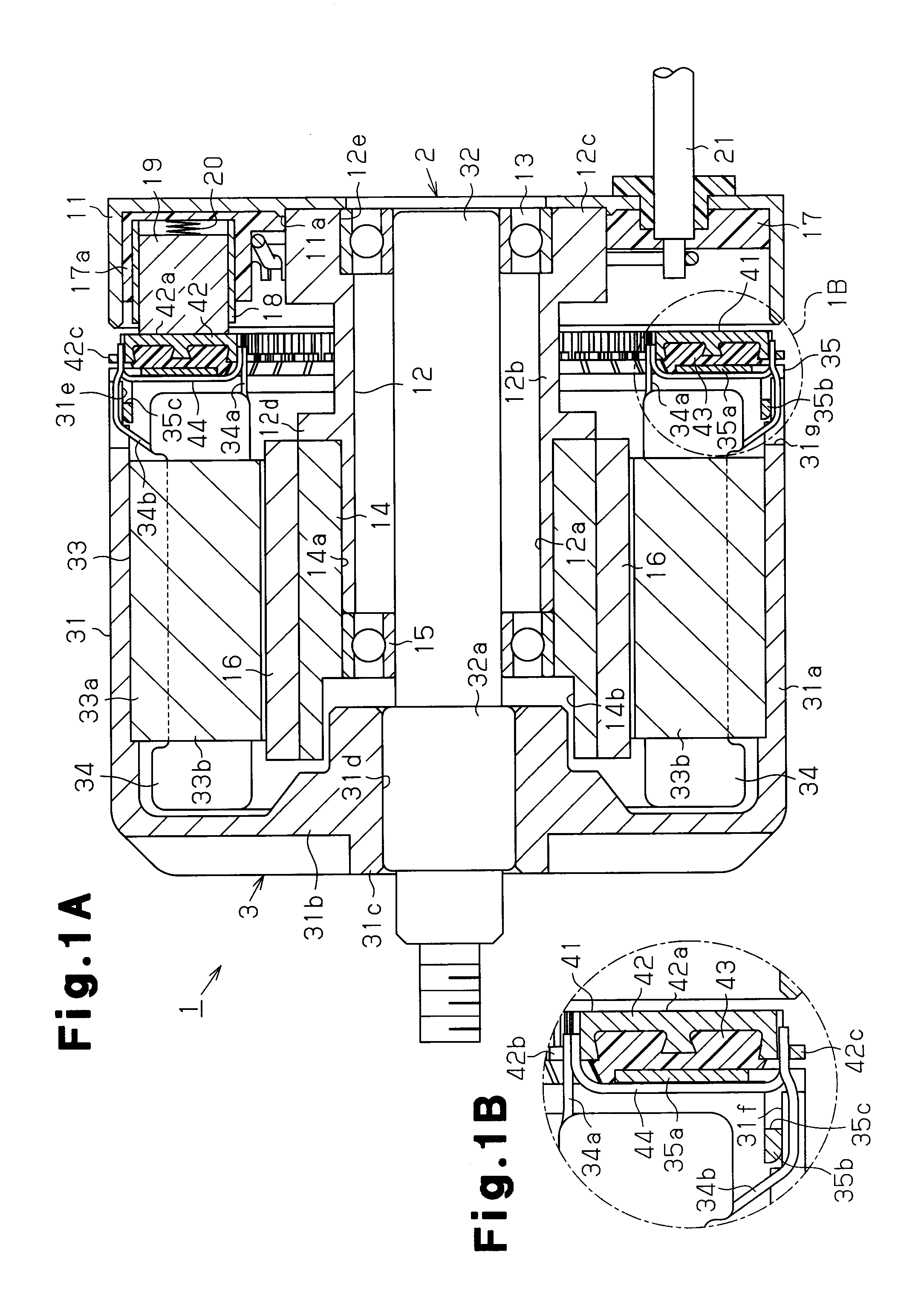
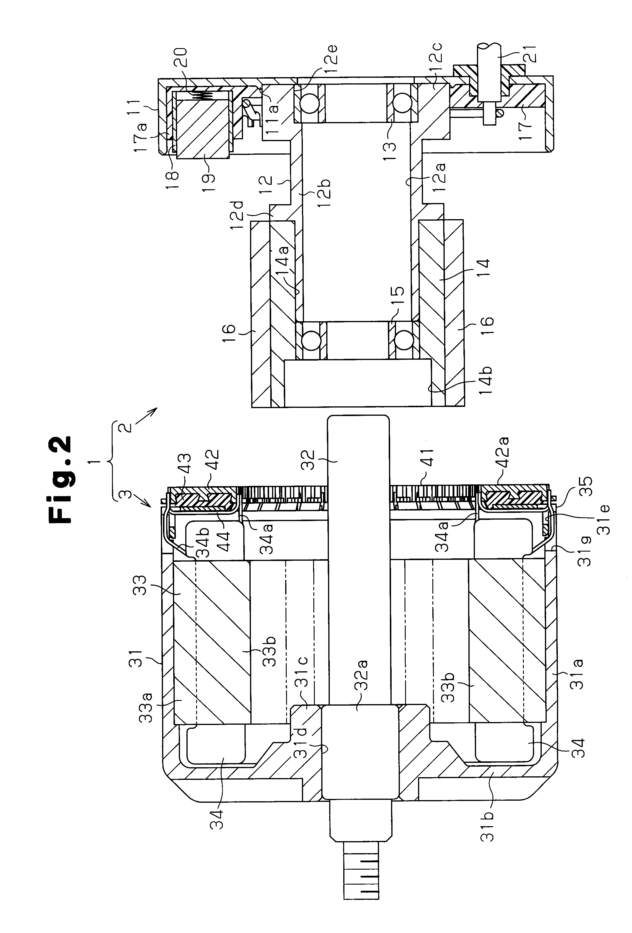
[0030]Hereinafter, the present invention will be described with reference to the drawings. FIG. 1A shows a direct-current motor 1 of this embodiment. As shown in FIG. 2, the direct-current motor 1 includes a stator 2 and a rotor 3 to be assembled to the stator 2.
[0031]As shown in FIG. 1A and FIG. 2, a stator housing 11 constituting the stator 2 is in a circular dish shape. On the bottom of the stator housing 11, a ring-shaped protruding ridge 11a protruding toward an opening side of the stator housing 11 is formed. This protruding ridge 11a is concentric with the bottom of the stator housing 11. A support member 12 is disposed on the inner side of the protruding ridge 11a.
[0032]The support member 12 includes a cylindrical main body 12b having an insertion hole 12a perforating axially through a radially central portion, a bearing holder 12c formed integrally on an end of the main body 12b close to the stator housing 11, and a flange 12d protruding radially outward from the substanti...
second embodiment
[0118]By manufacturing the stator 121 through this stator assembling step, the positional relationship in the radial direction between the permanent magnets 16 and the power supply brushes 133 is determined. In the manufactured stator 121, this positional relationship is kept constant. Thereafter, as in the case of the second embodiment, the rotor and the stator 121 are assembled to each other.
[0119]As described above, this third embodiment has the following advantages in addition to the advantages (1), (2), (4), (5), (6), and (7) of the first embodiment and the advantages (8) and (12) of the second embodiment.
[0120](14) Since the assembling directions of the brush holder 131, the cap 132, the power supply brush 133, and the coil spring 134 constituting the brush assembly 123 are unified in the same axial direction, the brush assembly 123 is easily manufactured. Therefore, the stator 121 is more easily manufactured.
[0121](15) Since each brush assembly 123 includes one each of the br...
fourth embodiment
[0136]In the fourth embodiment, the stator 181 includes one capacitor 182 and two choke coils 183 and 184 which function as a noise reduction member. However, the circuit elements of the noise reduction member are not limited to these. For example, the noise reduction member may include only one choke coil, or may include one each of choke coil and capacitor.
[0137]In the fourth embodiment, the noise reduction member of the stator 181 prevents generation of electromagnetic noise according to the rotating drive of the direct-current motor. However, the electromagnetic compatibility (EMC) may be improved by removing noise of a current to be supplied to the armature coils or preventing generation of electromagnetic noise according to the rotating drive of the direct-current motor. Therefore, for example, as a noise reduction member, a diode or a surge suppressor may be provided in the stator 181.
[0138]In the second through fourth embodiments, the pigtails 103a, 103b, and 153 may be in a...
PUM
| Property | Measurement | Unit |
|---|---|---|
| Force | aaaaa | aaaaa |
| Diameter | aaaaa | aaaaa |
| Magnetic field | aaaaa | aaaaa |
Abstract
Description
Claims
Application Information