Active phased array antenna for aircraft surveillance systems

a phased array, aircraft surveillance technology, applied in the direction of antennas, instruments, movable body antenna adaptation, etc., can solve the problems of system range and transmit power efficiency, transmission power loss affecting system transmit range, and the performance of the overall receiver system performance of the passive antenna array

Active Publication Date: 2008-05-29
GARMIN INT
View PDF89 Cites 26 Cited by
  • Summary
  • Abstract
  • Description
  • Claims
  • Application Information

AI Technical Summary

Benefits of technology

[0013]A need exists for an improved antenna system that does not experience excessive degradation of the receive system performance, system range or transmit power losses.

Problems solved by technology

Passive antenna arrays have experienced limitations in the overall receiver system performance, system range and transmit power efficiency.
The power efficiency of the transmitter is limited due, in part, to transmission losses suffered while conveying high power over the coaxial transmission lines.
The transmit power losses impact the system transmit range.
The losses may result from coaxial cable loss between the transmitter and the antenna array.
Losses may occur due to internal effects in the transceiver such as high power beamsteering or high power attenuation circuits inherent in previous TAS / TCAS designs that respectively do beam forming of directional antennas, and transmit power attenuation in a process known as Whisper-Shout.
Losses resulting from the coaxial cables and these other sources drive the need for high power amplifiers at the transmitter.
The system also experiences limitations in the receive range and receive sensitivity due to the losses and noise produced by the coaxial transmission line and associated circuit components at the receiver and transmitter that maintain desired performance characteristics of the remotely located passive antenna array.
For example, a conventional system may only be able to provide receive sensitivity for up to 90 Nautical miles.
The limited receive sensitivity is due in part to cable losses, in part to noise within the receive signal path and the like.

Method used


Image

  • Active phased array antenna for aircraft surveillance systems
  • Active phased array antenna for aircraft surveillance systems
  • Active phased array antenna for aircraft surveillance systems

Examples


Embodiment Construction

[0022]Embodiments of the present invention are described in connection with an automatic calibration system for a Traffic Avoidance System (TAS), or Traffic Collision Avoidance System (TCAS I and TCAS II). However, it is understood that the present invention may be utilized in other aircraft surveillance applications. In one implementation, the automatic calibration system operates with a four element active phased array antenna that includes four transmitter and receiver channels.

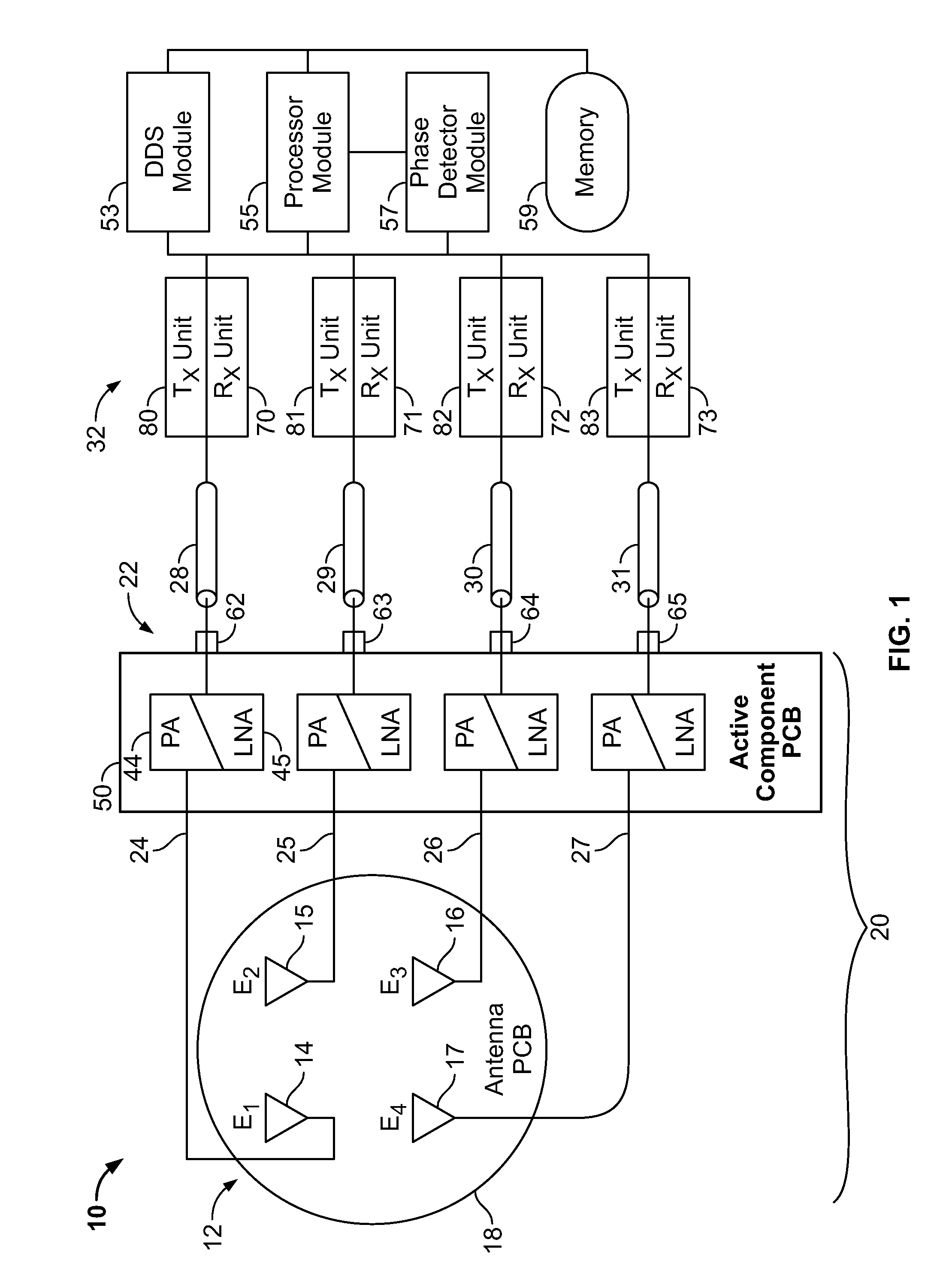
[0023]FIG. 1 illustrates a block diagram of an active phased array antenna system 10 that is formed in accordance with an embodiment of the present invention. The system 10 includes an antenna array 12 that comprises a plurality of antenna elements 14-17, each of which is mounted to a common antenna printed circuit board (PCB) 18. The antenna array 12 forms part of an antenna module 20 that is configured to be mounted to an aircraft. The antenna elements 14-17 transmit and receive RF transmit and receive s...


PUM


Abstract

An active antenna is provided that includes an antenna element for transmitting RF transmit signals at a predetermined effective radiated power (ERP). An antenna module is configured to be mounted to an aircraft, with the antenna element being mounted to the antenna module. A connector module is provided at the antenna module and is configured to be coupled to a communications link and receive electrical transmit signals from the communications link. A transmit path is provided within the antenna module and extends between the antenna element and the connector module. A power amplifier is provided on the antenna module along the transmit path. The power amplifier increases a power level of the electrical transmit signals, received from the communications link, by a predetermined amount sufficient to drive the antenna element to transmit the RF transmit signals at the predetermined ERP.

Description

BACKGROUND OF THE INVENTION[0001]The present invention generally relates to an active antenna system for use in an aircraft, and more particularly to an active phased array antenna system for use in an aircraft surveillance system.[0002]Today, systems exist for use in aircraft surveillance for collision avoidance and traffic alert. These conventional systems use active interrogation of Mode Select (Mode-S) and Air-Traffic Control Radar Beacon System (ATCRBS) transponders that can incorporate a passive phased array antenna. Conventional Mode-S and ATCRBS transponders transmit encoded messages containing information about the aircraft in response to interrogation signals received from ground based radar or from an aircraft with a Traffic Advisory System (TAS), or Traffic Collision Avoidance System (TCAS). When the transponder is not transmitting, it monitors for transmissions including interrogation signals.[0003]The Minimum Operating Performance Specifications (MOPS) for the TCAS II ...

Claims


Application Information

Patent Timeline
Patent Type & Authority Applications(United States)
IPC IPC(8): H01Q3/26
CPCG01S7/03G01S7/4017H01Q3/26G01S2013/0254H01Q1/28G01S13/9303G01S13/933
Inventor NEEDHAM, EDWARD W.MINDRUP, DAVID T.BLESSING, JOHN C.
Owner GARMIN INT
Why Eureka
Try Eureka