
Light device having LED illumination and electronic circuit board in an enclosure

a technology which is applied in the field of electronic circuit board and light device, can solve the problems of reducing the life of the light device, reducing the reducing the life so as to improve the efficiency and efficiency of the light source, reduce the cost of operation, and improve the effect of heat dissipation

Inactive Publication Date: 2008-05-29
LED GREEN POWER
View PDF15 Cites 65 Cited by
  • Summary
  • Abstract
  • Description
  • Claims
  • Application Information

AI Technical Summary

Benefits of technology

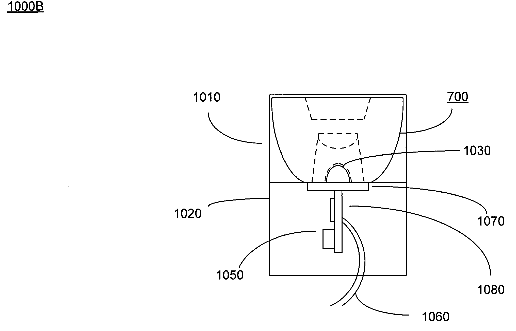
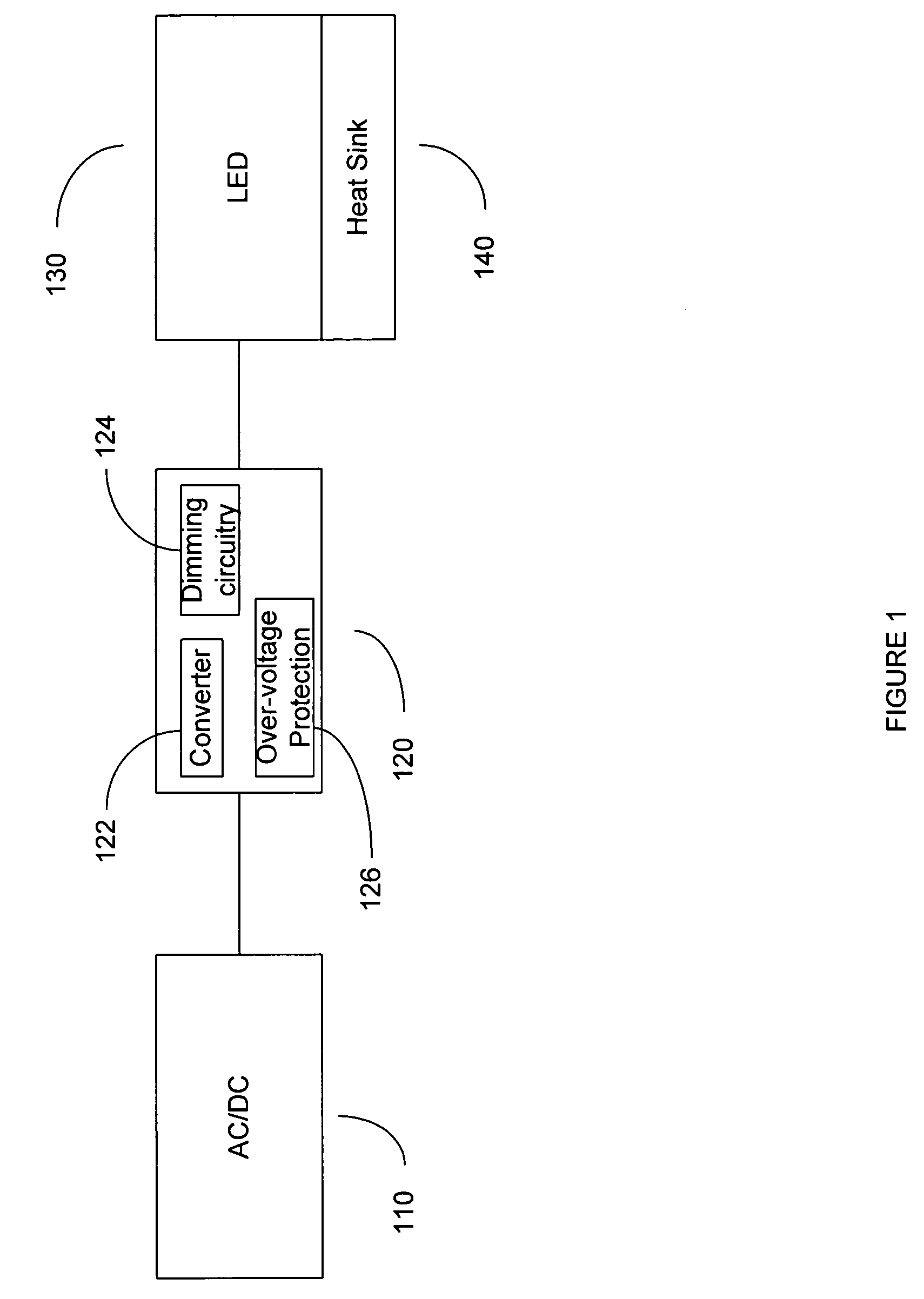
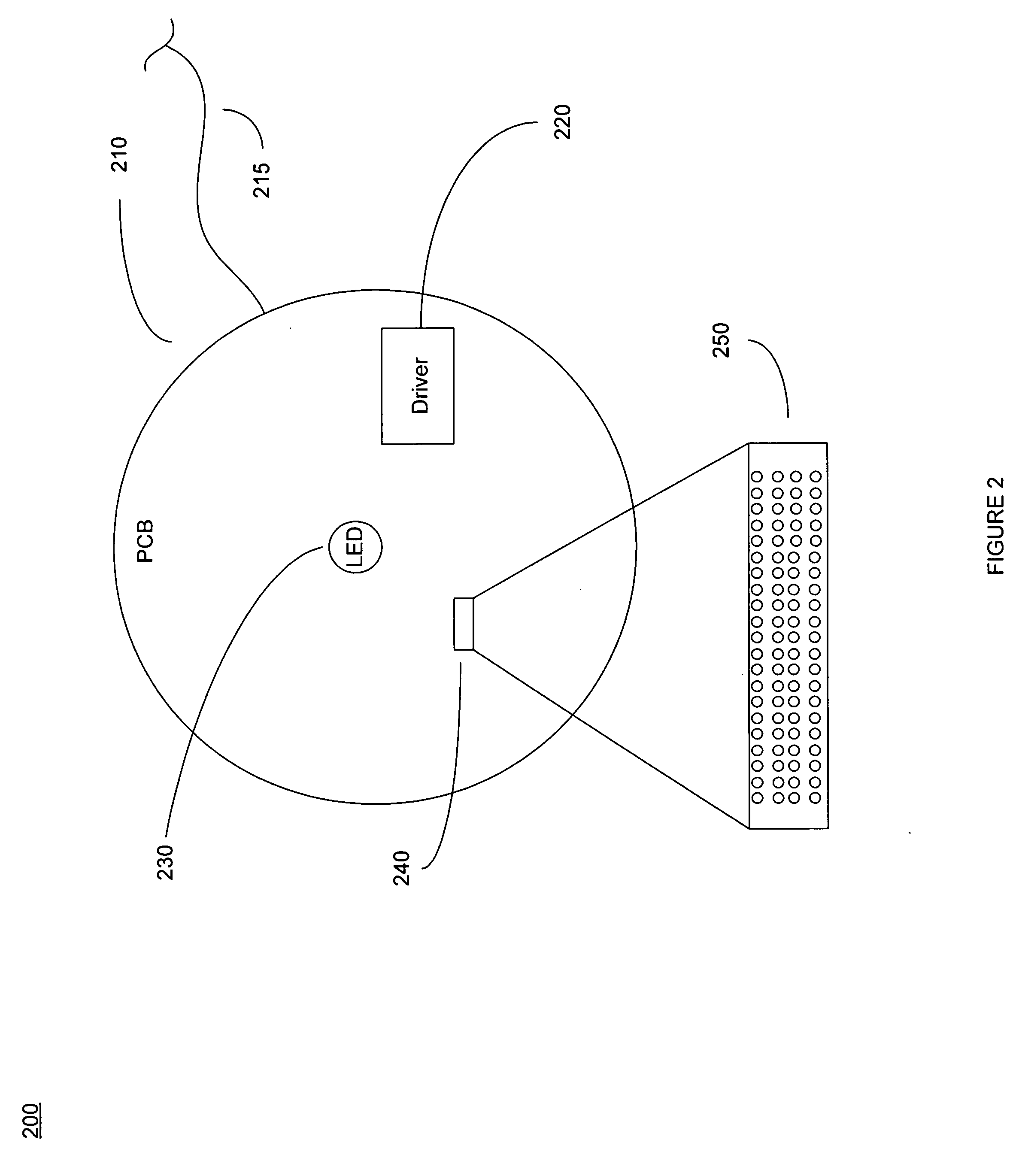
[0011]In one embodiment of the present invention, an LED engine is described that is compact and operable in one embodiment for low voltage and / or another embodiment for high voltage applications. The light engine is operable using a single electronic board which contains high power LED components (e.g., 250-1000 mA at 3.2 v). The single board LED engine is equipped with a heat sink for dissipating the heat generated from the one or more LEDs. In one embodiment, the heat sink is formed as an integrated layer or multiple layers of nickel and silver plates of the single board (e.g., PCB board). In other embodiments, the heat sink may be formed by a plurality of vias on the single board wherein the vias allow air flow to dissipate heat.
[0012]Embodiments of the present invention include a light engine also having driver circuitry that contains a converter on the single board for accepting multiple input voltages and converting to a voltage within the operable range of the LED(s). The light engine further includes an over voltage protection component for preventing potential damage to the LED components or other circuitry present on the single board resultant from an input voltage outside of the operating range. Furthermore, in one embodiment a dimming component is used that is operable with an external dimming component belonging to other electronic devices. In line voltage applications, a power converter which may be a transformer is also present within the light engine.
[0013]As a result, a flexible, compact and universal light engine (on a single piece PCB board) is provided which is operable with multiple input voltages, and wherein its components are protected from input voltage swings outside of their normal operating range. Additionally, the light engine and its dimming component are provided with added flexibility to be operable with external dimming components belonging to other electronic devices. The light engine also has integrated compact heat dissipation.
[0014]The high power LEDs also provide excellent light output at 250 to 1000 mA at 3.2 volts. The high light output coupled with the compact design of the light engine make it an excellent choice as a high efficiency light source for most lighting fixtures. The lighting engine can be used to readily replace the light source for most conventional lighting fixtures, whether it be high voltage or low voltage applications.

Problems solved by technology

Typically, a light emitting diode (LED) is designed to operate with no more than 30-60 milliwatts of electrical power because higher power reduces its lifespan and heat generated by the LED may damage its operation or render it inoperable.
High power LED components do not only help to conserve energy by virtue of their high efficiency but they produce more lumens per unit of energy as well.
Unfortunately, the higher the power the more heat is generated by the LED.
As a result, the lifespan of the LED may be reduced and if the generated heat is not addressed, the LED component may be damaged.
Unfortunately the higher the power used for an LED, the larger the semiconductor die size is needed along with a larger heat sink.
Using additional space for dissipating the heat renders the conventional LED lighting device bulky and not readily usable in small fixtures (e.g., a light fixture).
Moreover, conventional LED driver components are not equipped with a component stepping up or down the input voltage (e.g., converter) such that the LED can be used universally and without the need for an external transformer.
Moreover, LED driver components are in general not equipped with over voltage protection to protect the LED in case the input voltage swings outside of the converter's range.
Unfortunately, the dimming components are inoperable with external dimmers belonging to other electronic devices, hence they require their own corresponding external dimmers.
Conventional LED drivers and heat sinks are not readily adapted for existing light fixtures.
Accordingly, placing LED lighting component with its circuitry inside lighting fixtures and other structures is challenging with various space constraints and electrical incompatibility.
As a result, lighting fixtures utilizing LED light sources are not readily available in conventional lighting supply houses.

Method used


Image

  • Light device having LED illumination and electronic circuit board in an enclosure
  • Light device having LED illumination and electronic circuit board in an enclosure
  • Light device having LED illumination and electronic circuit board in an enclosure

Examples


Embodiment Construction

[0043]Reference will now be made in detail to embodiments of the present invention, examples of which are illustrated in the accompanying drawings. While the invention will be described in conjunction with these embodiments, it will be understood that they are not intended to limit the invention to these embodiments. On the contrary, the invention is intended to cover alternative, modifications and equivalents, which may be included within the spirit and scope of the invention as defined by the appended claims. Furthermore, in the following detailed description of the present invention, numerous specific details are set forth in order to provide a thorough understanding of the present invention. However, it will be evident to one ordinary skill in the art that the present invention may be practiced without these specific details. In other instances, well known methods, procedures, components, and circuits have not been described in detail as not to unnecessarily obscure aspects of t...


PUM


Abstract

A light device having a light source, lenses adjacent to the light source, a housing for securing the light source and the lenses, and a light fixture for securing the housing. The light source includes high efficiency light emitting diodes (LEDs), driver circuitry, and a heat sink mounted and integrated on a common board. The driver circuitry receives multiple input voltages, supplies an appropriate power signal, provides over-voltage protection and controls dimming for the LEDs. Lenses magnify and focus light emitting from the LEDs at a diffusion angle between 10° and 100°. The housing comprises a first and a second portion fittable together (e.g., threads, screws and openings). LEDs are operable between 250 mA to 1 A at 3.2 volts and produce at least 55 lumens per LED. The light fixture may be rotateable to adjust the direction of the light from the LED. The light fixture may be puck-shape.

Description

TECHNICAL FIELD[0001]Embodiments of the present invention relate to the field of electronics and lighting. More particularly, embodiments of the present invention relate to electronics and lighting devices that provide illumination using light emitting diode (LED).BACKGROUND ART[0002]Typically, a light emitting diode (LED) is designed to operate with no more than 30-60 milliwatts of electrical power because higher power reduces its lifespan and heat generated by the LED may damage its operation or render it inoperable. However, in recent years, LED components with much larger semiconductor die sizes have been developed to allow operation with higher power inputs.[0003]High power LED components are desirable because they produce more light and use less power over conventional light sources. For example, LED components use 5-10 times less energy than a florescent light and produce significantly more lumens. For instance, Lumileds has developed a 5-watt LED available with efficiencies ...

Claims


Application Information

Patent Timeline
IPC IPC(8): F21V29/00H05B45/50
CPCF21K9/00F21V21/30F21V27/00F21V29/004F21Y2101/02H05B33/0803F21V29/74H05B33/0857H05B33/0887H05K1/0272H05K1/05Y02B20/341F21V23/005H05B33/0815F21Y2115/10F21K9/69F21V29/89F21V29/70H05B45/50H05B45/20Y02B20/30H05B45/325H05B45/355H05B45/3725H05B45/375
Inventor MCCLELLAN, THOMAS
Owner LED GREEN POWER
Learn More