Ground source energy generator

a generator and ground source technology, applied in the manufacture/treatment of thermoelectric devices, electrical apparatus, thermoelectric devices with peltier/seeback effects, etc., can solve the problems of low efficiency, negative impact on the environment, and limited power supply capacity, so as to reduce heat loss and high thermal conductivity

Inactive Publication Date: 2008-06-05
SCHICK DAVID B +1
View PDF10 Cites 22 Cited by
  • Summary
  • Abstract
  • Description
  • Claims
  • Application Information

AI Technical Summary

Benefits of technology

[0019]The system may further include a fan element, adapted to force air across the first tank. Further, the second tank may be insulated to reduce heat loss. The fluid may be a liquid metal or a fluid with a high level of thermal conductivity.

Problems solved by technology

Such sources can be costly and can have a negative impact on the environment.
However, these alternative sources also have a number of drawbacks, such as being limited in their efficiency, usefulness, and the amount of power they can provide.
Although these devices have been well known for many years, they are typically only used when either very high temperature sources are available (for example greater than 100° C.) or when very small amounts of power are required.
The primary reason for this is that these devices tend to have very poor efficiencies when the temperature difference is small.
While the Hiller et al. system makes use of temperature cycles in the environment (for example daily temperature variations of the atmosphere) to generate thermoelectric power, this phase-change technique is limited in that it requires the temperature of the environment to swing above and below the temperature of the phase-change mass during the course of the relevant time period (e.g., a day).
This can greatly limit the efficiency of the system.
Furthermore, the Hiller et al. system does not take advantage of the natural temperature differential between the ground and air.
As such, it may not be ideal for use in stationary or remote locations.

Method used


Image

  • Ground source energy generator
  • Ground source energy generator
  • Ground source energy generator

Examples


Embodiment Construction

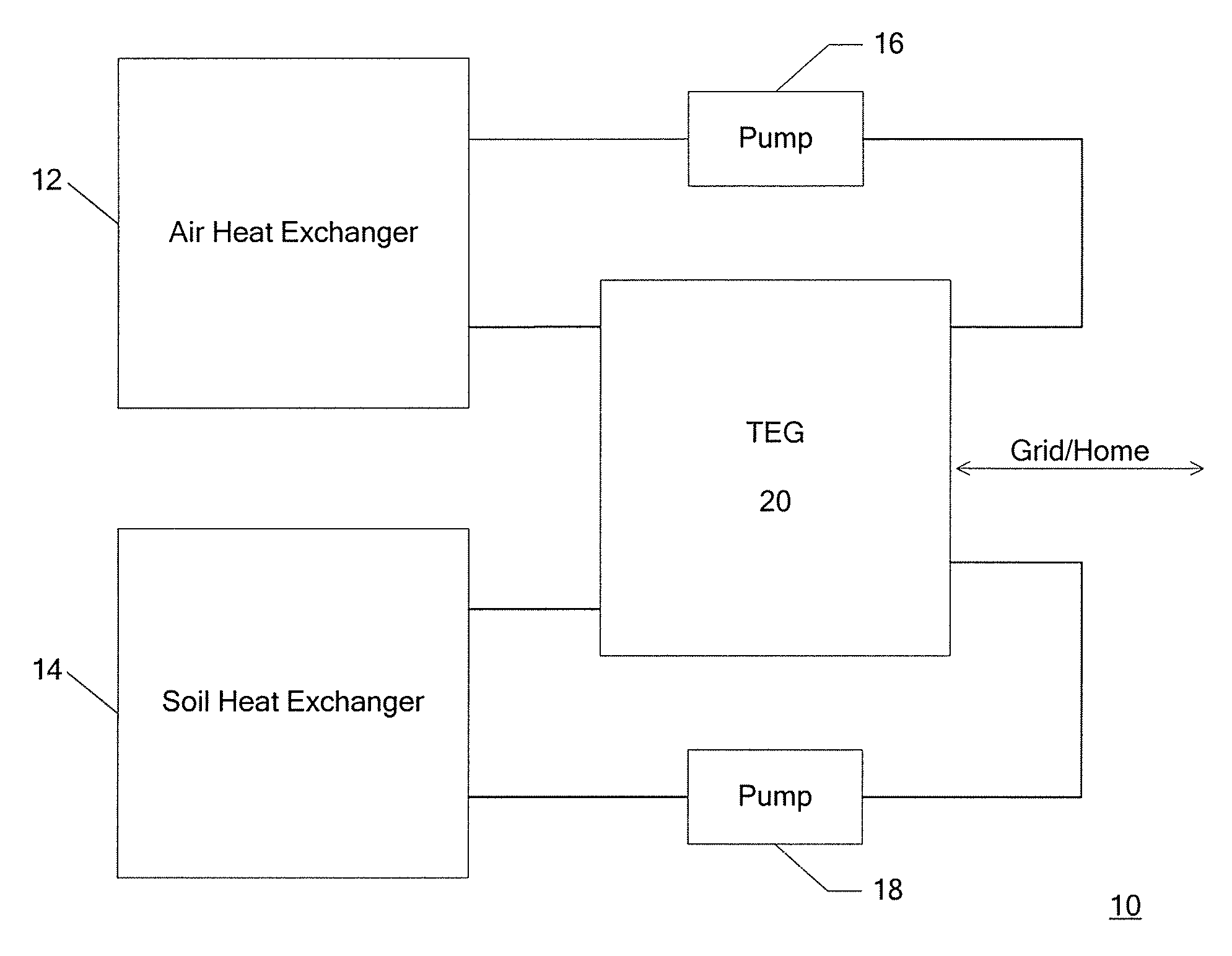
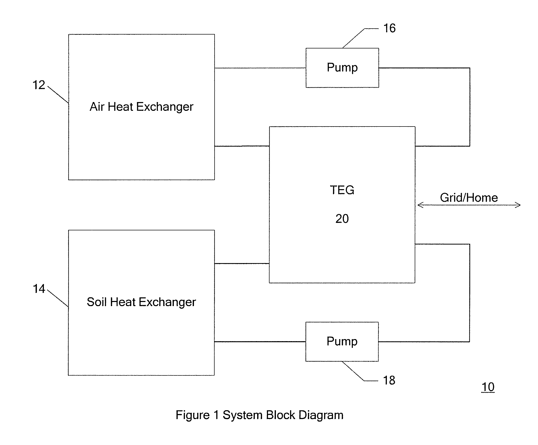
[0035]The present invention according to one embodiment is directed to a system for harvesting thermoelectric energy using fluids. FIG. 1 shows a device 10 which harvests energy from the temperature difference between soil and air. At a depth of two meters or greater, the soil temperature of the earth typically remains a fairly stable 8° C., while the air temperature varies with season, climate and time of day.

[0036]The device 10 includes an air heat exchanger 12 and a ground heat exchanger 14, both having associated pumps 16, 18, respectively. The device 10 further includes a thermoelectric generator (TEG) assembly 20. Fluid is pumped through the air heat exchanger 12 where it is brought to the air temperature, using either natural or forced convection. At the same time, fluid is pumped through the ground heat exchanger 14 where it is brought to the ground temperature. The ground-side fluid and the air-side fluid are then simultaneously pumped across both sides of the TEG assembly ...


PUM


Abstract

A method for generating electricity from a ground source. A temperature differential is created across a thermoelectric generator by passing a first fluid that has been maintained at air temperature over one side of the generator, and passing a second fluid that has been maintained at ground temperature over the other side of the generator. Electricity is generated from a voltage induced by the temperature differential across the thermoelectric generator.

Description

CROSS-REFERENCE TO RELATED APPLICATIONS[0001]This application claims the benefit of priority based on U.S. provisional application No. 60 / 859,711, filed Nov. 17, 2006, and U.S. provisional application No. 60 / 878,803, filed Jan. 5, 2007, both of which are hereby incorporated by reference in their entireties, as if fully set forth herein.FIELD OF THE INVENTION[0002]The present invention generally relates to systems, methods, apparatuses, and programs for generating energy from a ground source.RELATED ART[0003]Electrical energy is, of course, widely used in today's society for the purposes of powering human technologies. Much of the electrical energy in use today is generated from energy sources such as coal, nuclear power, natural gas, hydroelectric power, and petroleum. Such sources can be costly and can have a negative impact on the environment. Because of this, alternative sources of energy have been contemplated and utilized, including solar energy and wind generators. However, th...

Claims


Application Information

Patent Timeline
Patent Type & Authority Applications(United States)
IPC IPC(8): H01L35/02
CPCH01L35/30H10N10/13
Inventor SCHICK, DAVID B.KEMENY, SABRINA
Owner SCHICK DAVID B
Why Eureka
Try Eureka