Electrochromic device
a technology of electrochromic devices and electrodes, applied in the direction of instruments, coatings, nanotechnology, etc., can solve the problems of not necessarily providing films, lack of precise control of film composition and thickness, and difficulty in producing films on a large scal
- Summary
- Abstract
- Description
- Claims
- Application Information
AI Technical Summary
Problems solved by technology
Method used
Image

Examples
example 1
Preparation of a Working Electrode Coating Composition
[0126]Dispersed solutions having the amounts of components seen in Table 1 below were prepared as follows: Titanium dioxide nanopowder, ST-01 and ST-21 were premixed using a T 25 ULTRA-TURRAX® Rotor-Stator high-shear mixer (IKA® Works, Inc., Wilmington, N.C.) with aqueous solutions of modified viologen (prepared as given above). The mixture was further dispersed by the use of a microfluidizer® with serial 250 μm and 85 μm interaction chambers (Microfluidics, Newton, Mass.) operated at about 30,000 psi for up to 8 passes. The XRD diameters of the ST-01 and ST-21 are 7 and 20 nm respectively.
TABLE 1TiO2 / viologen aqueous dispersion compositionCviologen (mM)% wt ST-01% wt ST-21Dispersion 125032Dispersion 250220Dispersion 350202
[0127]The dispersed solutions, Dispersion 1, 2, and 3, were then utilized to form coating compositions. The main formulation compositions (% wt) are listed in table 2 below. The METHOCEL used in the formulation...
example 2
Formation of Films
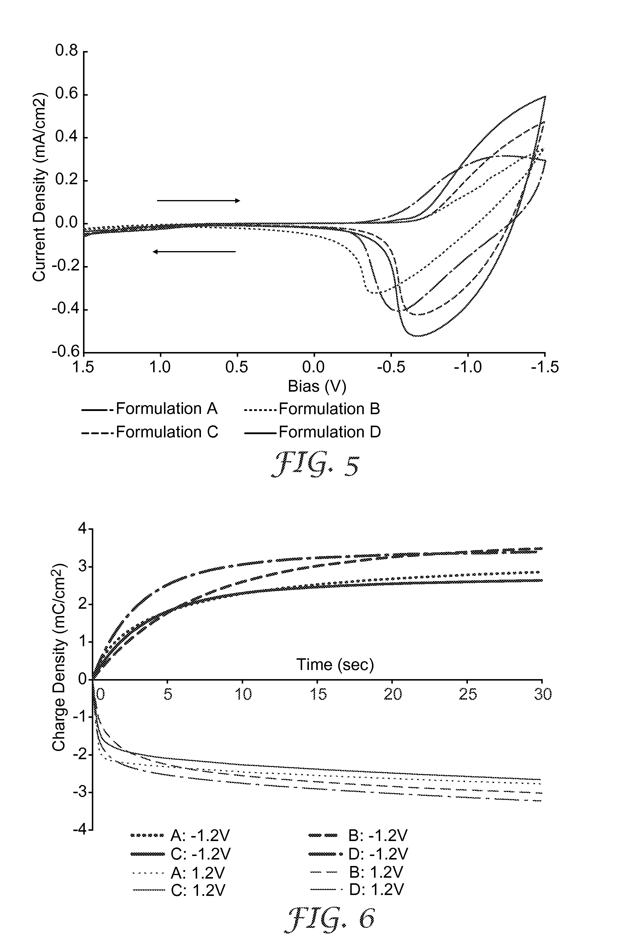
[0128]1″1″ films of formulations A, B, C, and D were printed onto ITO glass substrates (50Ω / □) by screen printing using polyester of stainless mesh, mesh size selected for the desired film thickness. The printed wet film was dried at 80° C. for 5 min. The dried film thickness was about 5 μm. The dried film was then soaked in methanol at 40° C. for 5 min. After air drying, the rinsed film was finally dried at 80° C. for 5 min. This film was used as the working electrode (W.E.) in the device and was characterized in Example 3 below.
example 3
Characterization of TiO2 Films
[0129]Experiments were carried out to determine the interfacial area of the low temperature TiO2 electrode films formed in Example 2 above. Nitrogen (N2) adsorption / desorption experiments were carried out. A sintered electrode was prepared for comparison. A coating composition that contains a large amount (binder:TiO2=0.45) of organic binder (including poly(ethylene glycol) (40 wt-%) and METHOCEL E 50 (methocellulose ether)(10 wt-%) was prepared. The sintering temperature was 450 C.°, which was high enough to burn the binder completely and fuse the neighboring TiO2 particles together. The coating composition for the sintered TiO2 film utilized TiO2 colloidal dispersion STS-01 from ISK. The particles in STS-01 dispersion have the same average size as in ST-01 powder (7 nm).
[0130]A low temperature electrode film formed from Formulation B in Example 2 and a sintered electrode made as discussed above were scraped off from their substrates. The powder sample...
PUM
| Property | Measurement | Unit |
|---|---|---|
| Pore size | aaaaa | aaaaa |
| Pore size | aaaaa | aaaaa |
| Thickness | aaaaa | aaaaa |
Abstract
Description
Claims
Application Information
 - Generate Ideas
- Intellectual Property
- Life Sciences
- Materials
- Tech Scout
- Unparalleled Data Quality
- Higher Quality Content
- 60% Fewer Hallucinations
Browse by: Latest US Patents, China's latest patents, Technical Efficacy Thesaurus, Application Domain, Technology Topic, Popular Technical Reports.
© 2025 PatSnap. All rights reserved.Legal|Privacy policy|Modern Slavery Act Transparency Statement|Sitemap|About US| Contact US: help@patsnap.com