Power Converter

a power converter and converter technology, applied in the direction of electrical apparatus construction details, solid-state devices, semiconductor devices, etc., can solve the problem that the volume of the power converter cannot be increased excessively, and achieve the effect of preventing the volume of the power converter from increasing

Active Publication Date: 2008-06-05
HITACHI ASTEMO LTD
View PDF7 Cites 157 Cited by
  • Summary
  • Abstract
  • Description
  • Claims
  • Application Information

AI Technical Summary

Benefits of technology

[0006]The output required for the rotary electric machine is increased and in correspondence to it, the power supplied to the rotary electric machine is apt to increase. The internal heat of the power converter for controlling the aforementioned supply power is also apt to increase. It is necessary to take a countermeasure for the internal temperature rise of the power converter accompanying the increase in the heat. On the other hand, the power converter for vehicle must be installed in the limited space of the vehicle and the volume of the power converter cannot be increased excessively. Therefore, it is necessary to examine so as to make the power converter comparatively compact.
[0007]An object of the present invention is to provide a converter for suppressing an increase in the volume as far as possible.
[0008]In the present invention, a power semiconductor circuit in which a coolant path structure forms a coolant path for letting a coolant pass, and a capacitor connected to a DC circuit is arranged on one side of the coolant path structure, and a power semiconductor chip for converting DC power to AC power is provided is installed on the other side of the coolant path structure. By use of this structure, the cooling ability of the power converter can be improved and the volume of the power converter can be suppressed from increasing.
[0010]According to the present invention, the volume of the power converter can be prevented from increasing.

Problems solved by technology

On the other hand, the power converter for vehicle must be installed in the limited space of the vehicle and the volume of the power converter cannot be increased excessively.

Method used


Image

  • Power Converter
  • Power Converter
  • Power Converter

Examples


Embodiment Construction

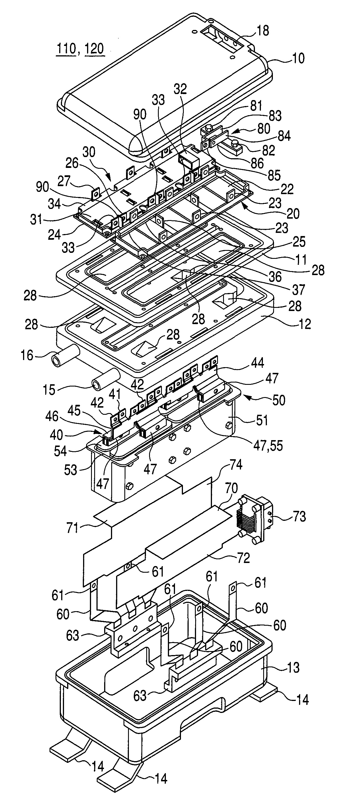
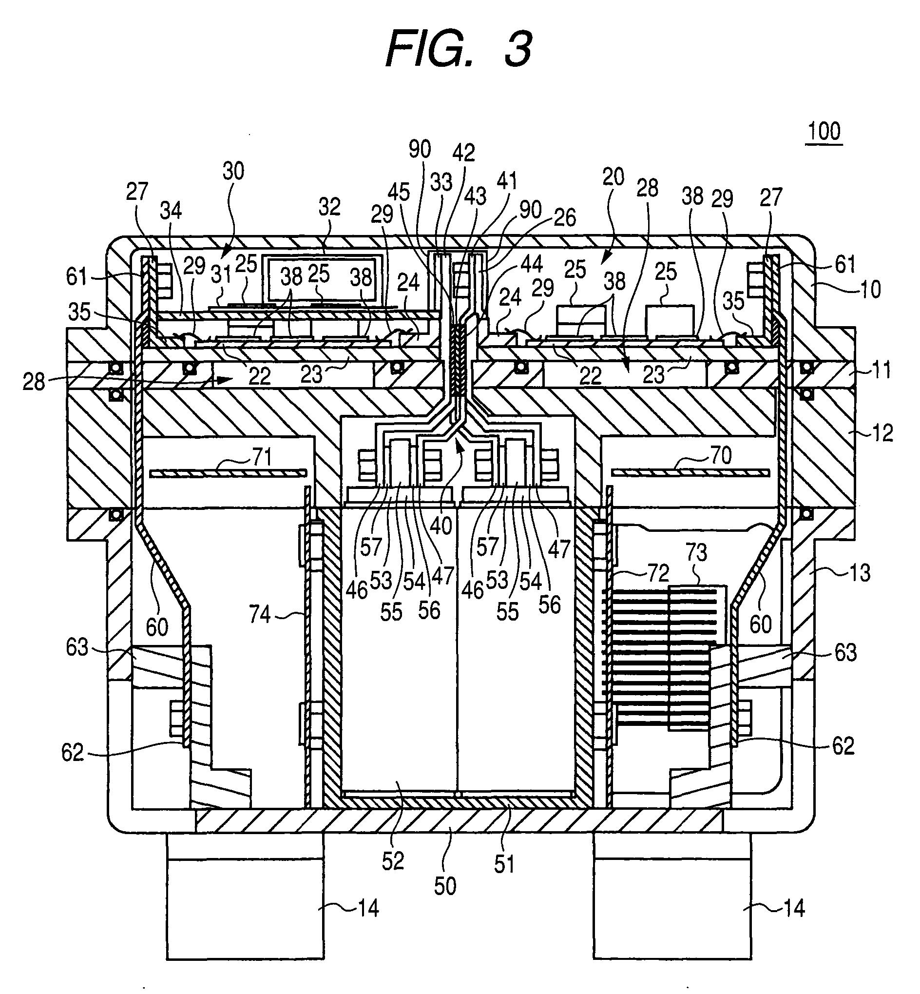
[0031]The embodiments explained hereunder have the effect of improving the cooling ability of the power converter and also the effects indicated below.

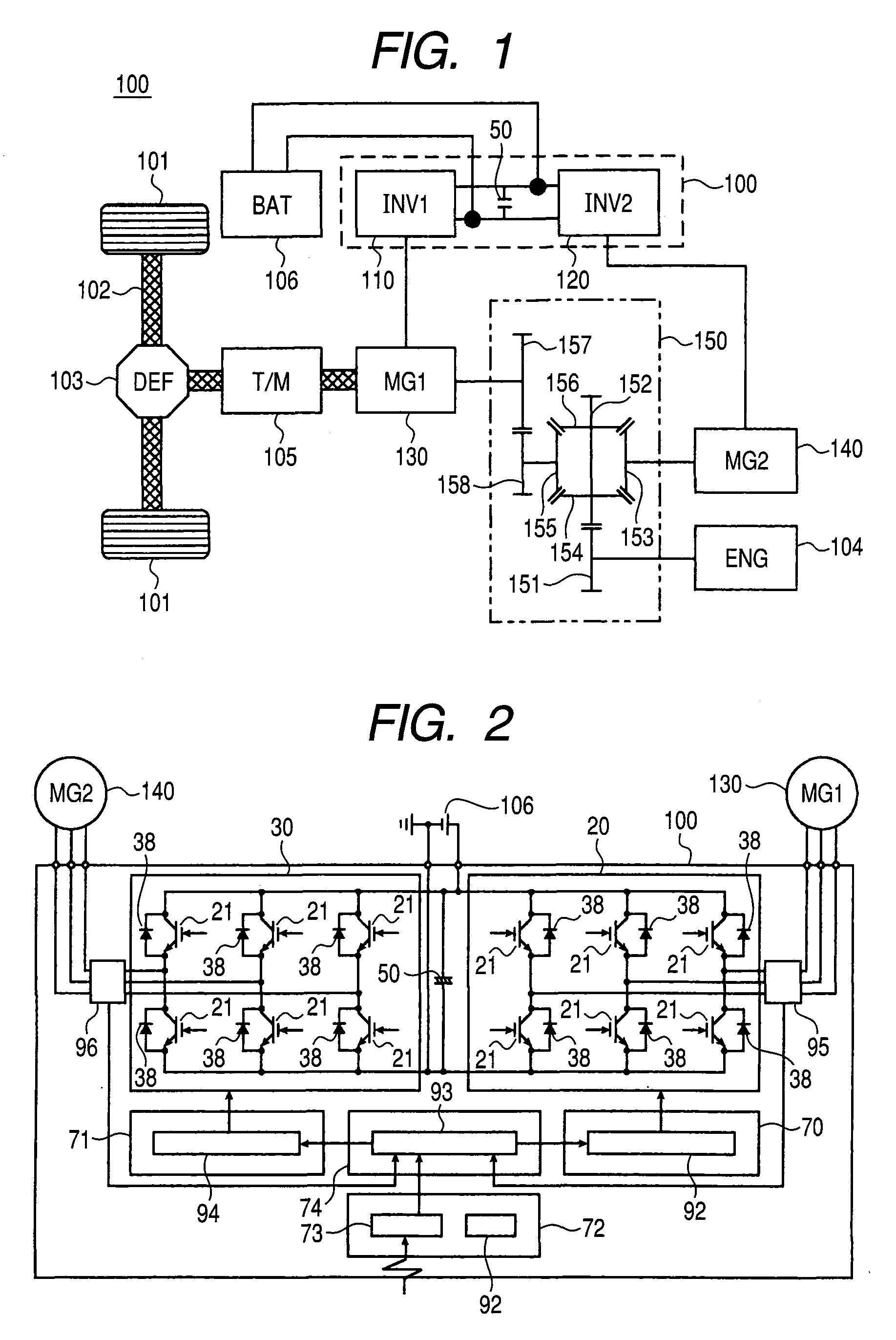
[0032](1) The structure of the embodiments has an effect of reducing the volume of the power converter. For example, the arrangement of the power semiconductor circuit, capacitor, and coolant path structure can be stored in a comparatively small volume and the overall volume of the power converter can be made smaller.

[0033](2) The internal inductance of the power converter can be made smaller. Particularly, the inductance of the DC circuit for connecting the power semiconductor circuit and capacitor can be made smaller. The voltage rise based on the on operation or off operation of the power semiconductor circuit is proportional to a change in the inductance or current. In the embodiments indicated below, the internal inductance of the power converter can be made smaller, so that even if the on or off operation speed of the power semi...


PUM


Abstract

First and second bases and composing a coolant path structure are arranged at the middle stage of the power converter, and semiconductor modules and a capacitor are arranged on both surfaces of the coolant path structure. Furthermore, through-holes are formed in the first and second bases, and cables of DC and AC circuits are laid via the through-holes.

Description

CLAIM OF PRIORITY[0001]The present application claims priority from Japanese application serial No. 2006-298375, filed on Nov. 2, 2006, the content of which is hereby incorporated by reference into this application.FIELD OF THE INVENTION[0002]The present invention relates to a power converter for converting DC power to AC power or a power converter for converting AC power to DC power.BACKGROUND OF THE INVENTION[0003]As a system that wheels are driven by output of a rotary electric machine and a vehicle travels, there are a hybrid system of driving wheels on the basis of output of an engine or both engine and rotary electric machine and a system of driving wheels only by rotary electric machine. In either of the systems, the DC power is converted to AC power by the power converter and the AC power is supplied to the rotary electric machine for driving wheels. On the basis of the supplied power, the rotary electric machine generates rotating torque, and the wheels are driven by the ro...

Claims


Application Information

Patent Timeline
Patent Type & Authority Applications(United States)
IPC IPC(8): H05K7/20H02M7/537
CPCH05K7/20927H02M7/003H01L2224/48137H01L2224/48472H01L2224/49111H01L2924/1305H01L2924/13055H01L2924/13091H01L2224/48139H01L2924/19107H01L2924/00
Inventor NAKAMURA, TAKAYOSHINAKATSU, KINYASAITO, RYUICHISUGA, TAKASHIFUNATO, HIROKI
Owner HITACHI ASTEMO LTD
Why Eureka
Try Eureka