
Lateral-flow waste gas treatment device using nonthermal plasma

Inactive Publication Date: 2008-06-05
INST NUCLEAR ENERGY RES ROCAEC
View PDF10 Cites 23 Cited by
  • Summary
  • Abstract
  • Description
  • Claims
  • Application Information

AI Technical Summary

Benefits of technology

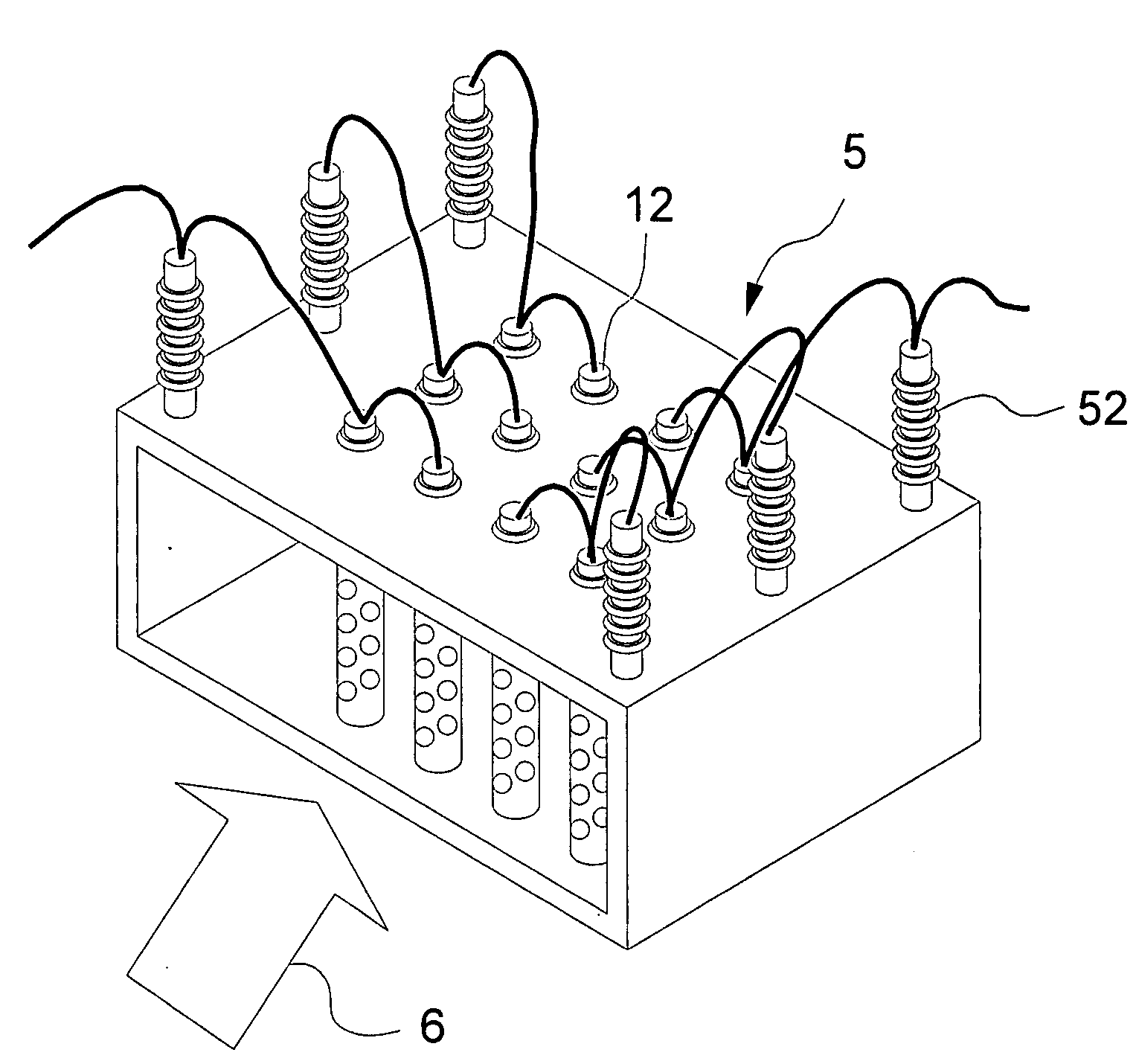
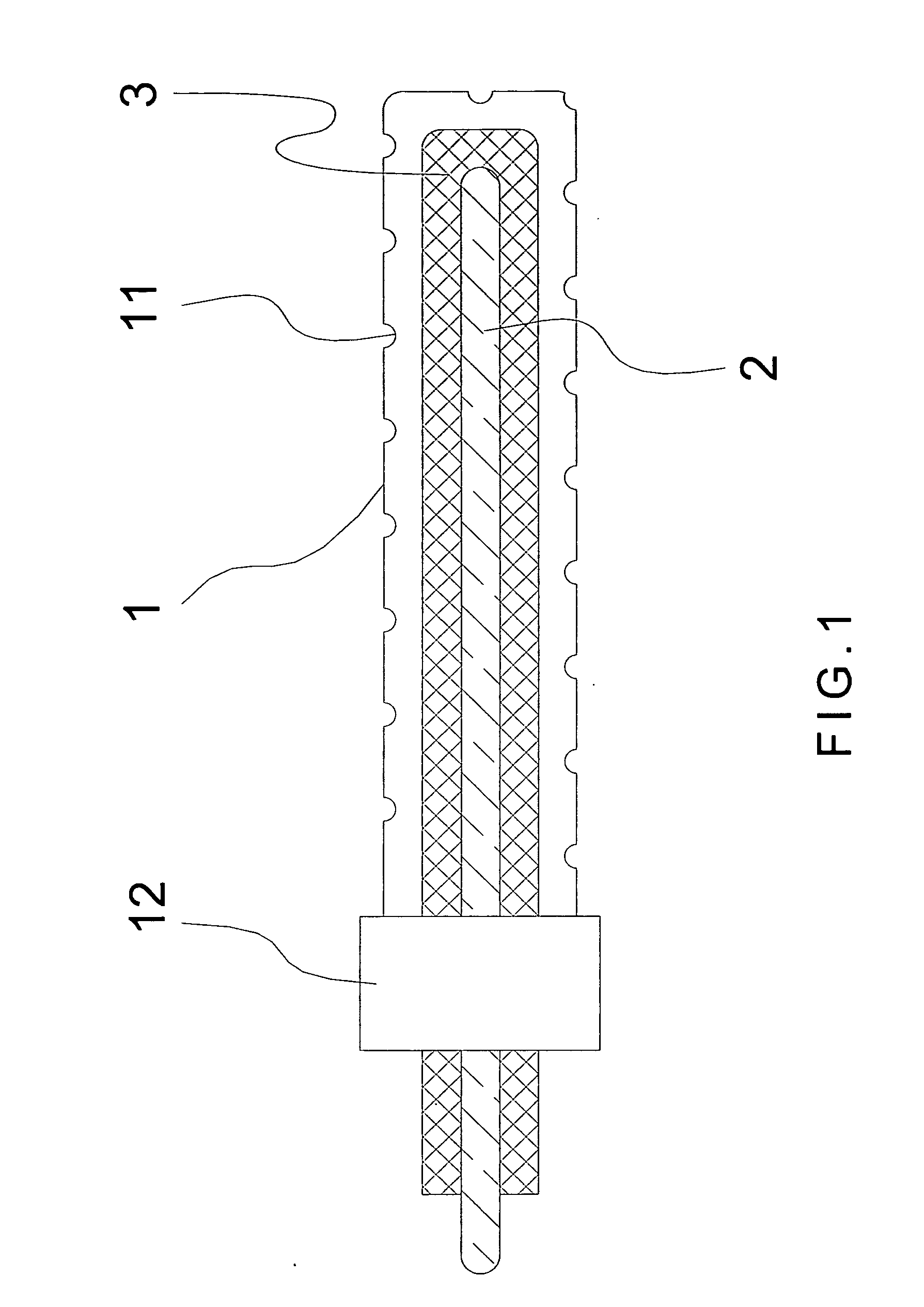
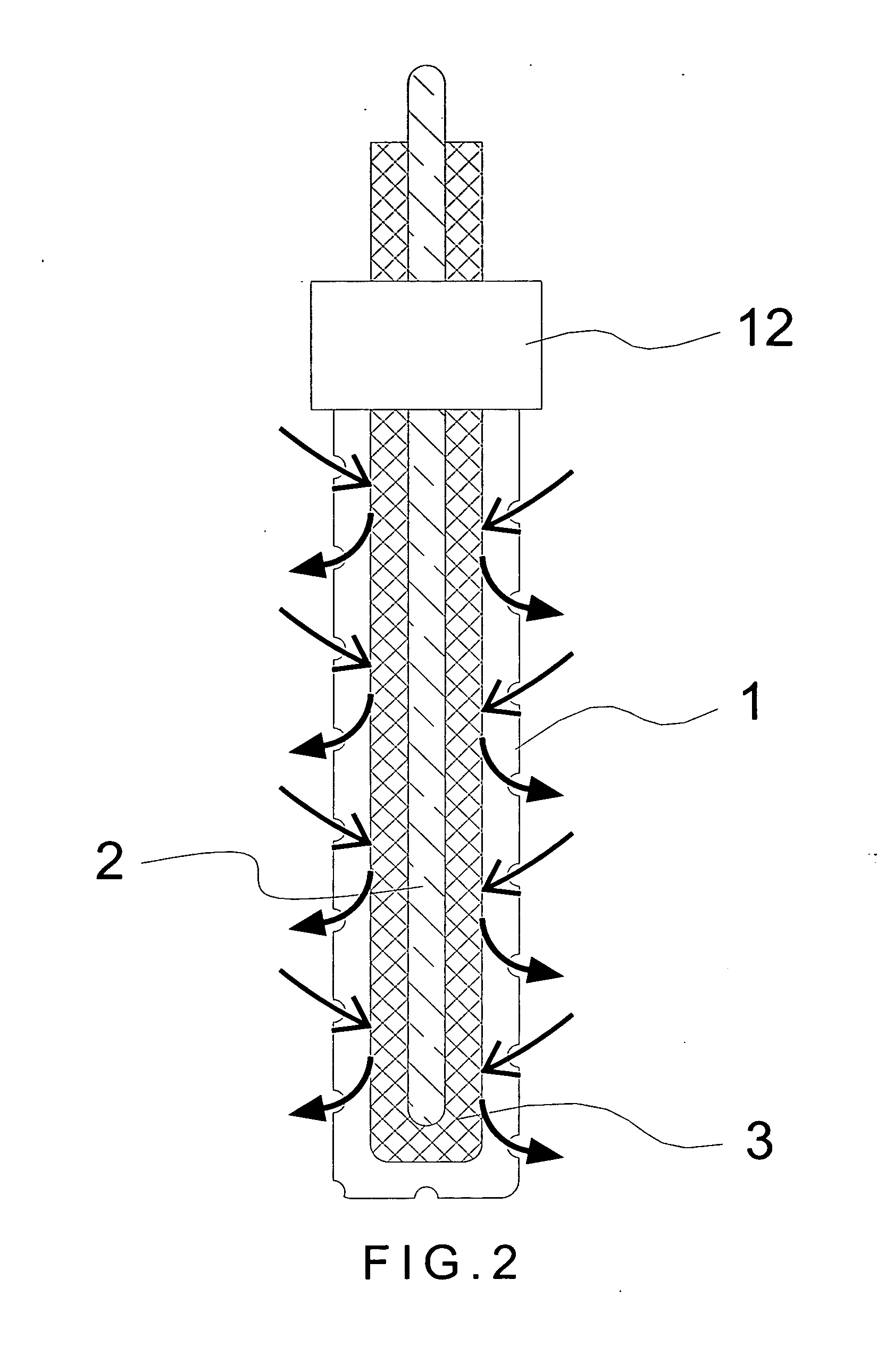
[0006]To achieve the above purpose, the present invention is a lateral-flow nonthermal plasma waste gas treatment device, comprising a plurality of lateral-flow DBD reactor units in a serial and parallel connection; and a plurality of airflow stoppers between lateral-flow DBD reactor units, where the lateral-flow DBD reactor unit comprises a perforated outer electrode, a center electrode, an insulating layer and a high voltage power source; the perforated outer electrode is a grounding cathode whose surface has a plurality of through holes; the center electrode is an anode inside the outer electrode; the insulating layer is located between the perforated outer electrode and the center electrode; the high voltage power source is coup led with the perforated outer electrode and the center electrode; and a required NTP is provided through a breakdown voltage discharging between the perforated outer electrode and the center electrode by using lateral-flow reactor units which is serial and parallel arranged to process a great amount of waste gas with an easy assembly and a low cost. Accordingly, a novel lateral-flow waste gas treatment device using nonthermal plasma DBD reactor units is obtained.

Problems solved by technology

The flat plasma reactor has a smooth gas flow, but discharging uniformity is weakened owing to increase in the flat area; and so its efficiency and flow amount is reduced.
Hence, it is rarely used to process a great amount of waste gas.
Yet, especially in processing a great amount of waste gas, owing to the too high cost to produce the high voltage short pulse with increased high power, it is not economically competitive on applying this method.
When enlarging a pipe's diameter to process a great amount of waste gas, the applied high voltage may be increased to an undesirable degree, not to mention the high operation cost in maintenance and safety assurance owing to the severe insulation protection.
However, settlement of the high-voltage wires, distribution of the gas flow and related maintenance considerations are all critical as well, so that complexity of the whole system increases which follows with heightened difficulties.
Hence, the prior arts do not fulfill users' requests on actual use.

Method used


Image

  • Lateral-flow waste gas treatment device using nonthermal plasma
  • Lateral-flow waste gas treatment device using nonthermal plasma
  • Lateral-flow waste gas treatment device using nonthermal plasma

Examples


Embodiment Construction

[0012]The following description of the preferred embodiment is provided to understand the features and the structures of the present invention.

[0013]Please refer to FIG. 1, which is a sectional view showing a lateral-flow DBD reactor unit of a preferred embodiment according to the present invention. As shown in the figure, the present invention is a lateral-flow waste gas treatment device using a nonthermal plasma, comprising a plurality of lateral-flow DBD reactor units and a plurality of airflow stoppers (not shown in the figure), where the lateral-flow reactor units comprises a perforated outer electrode 1, a center electrode 2, an insulating layer 3 and a high voltage power source 4; and the lateral-flow DBD reactor units can be arranged and integrated a serial and parallel connection to process waste gas which is flowed through a high-voltage discharging area interacting with the nonthermal plasma generated within.

[0014]The perforated outer electrode 1 is a grounding cathode an...


PUM

PropertyMeasurementUnit
Fractionaaaaaaaaaa
Fractionaaaaaaaaaa
Fractionaaaaaaaaaa

Abstract

A lateral-flow dielectric barrier discharging reactor unit is designed to effectively process waste gas. Nonthermal plasma is obtained through high voltage gas breakdown for processing the waste gas. Reactor units can be arranged and integrated in a serial and / or parallel way with flow uniformity and smoothness for processing a great amount of waste gas with merits of simplicity and low cost.

Description

FIELD OF THE INVENTION [0001]The present invention relates to a device for waste gas treatment; more particularly, relates to obtaining a nonthermal plasma through a high voltage discharging device for processing waste gas.DESCRIPTION OF THE RELATED ARTS[0002]A nonthermal plasma (NTP) device used for processing waste gas is obtained first by high temperature free electrons through high-voltage discharging in a gas, and then the electrons collides with other gas molecules to form free radicals, like excited atom and molecules of N, O, OH and O3, for oxidizing or reducing waste gas into harm less gas rapidly. In the whole process, the energy used is mainly added on the electrons while the gas molecule itself has little increase in energy; so, the temperature of the electrons is much higher than that of the gas molecule, which is thus called NTP. By using this method, a great amount of low-concentration polluted waste gas can be processed with saved energy yet high efficiency.[0003]A d...

Claims


Application Information

Patent Timeline
IPC IPC(8): B01D53/32
CPCB01D53/32H05H1/24B01D2259/818H05H1/2406
Inventor TZENG, CHIN-CHINGCHEN, SHIAW-HUEI
Owner INST NUCLEAR ENERGY RES ROCAEC
Learn More