Optical disk apparatus

a technology of optical disk and optical disk, which is applied in the direction of digital signal error detection/correction, instruments, recording signal processing, etc., can solve the problems of increasing manufacturing costs, and affecting the operation of optical disk apparatus. , to achieve the effect of reducing coma and correcting the til

Inactive Publication Date: 2008-06-05
FUNAI ELECTRIC CO LTD
View PDF6 Cites 4 Cited by
  • Summary
  • Abstract
  • Description
  • Claims
  • Application Information

AI Technical Summary

Benefits of technology

[0018]An object of the present invention is to provide an optical disk apparatus which can acquire an appropriate tilt correction magnitude without adding a tilt sensor or the like device for tilt servo anew, and by easy processing of short time period.
[0026]According to this configuration, the optical disk apparatus in the invention comprises the liquid crystal device for correcting a coma (namely, the aberration) ascribable to the tilt of the optical disk. In addition, the tilt correction circuit determines the magnitude of the voltage to be applied across the electrodes included in the liquid crystal device, in accordance with the tilt correction magnitude, so as to decrease the coma, thereby to correct the tilt.

Problems solved by technology

This incurs the drawback that an information track on the disk as ought to be read cannot be read.
However, in a case where such a sensor is assembled in the optical disk apparatus anew, there have been the problems that the internal structure of the optical disk apparatus is liable to become complicated, and that the manufacturing cost thereof increases.
For this reason, there have been the problems that a time period till the completion of the tilt adjustment processing becomes long, and that the contents of the detection processing are liable to become complicated.

Method used


Image

  • Optical disk apparatus
  • Optical disk apparatus
  • Optical disk apparatus

Examples


Embodiment Construction

[0043]Now, embodiments of the present invention will be described with reference to the drawings. Incidentally, the embodiments illustrated here are mere examples, and the invention shall not be restricted to these embodiments.

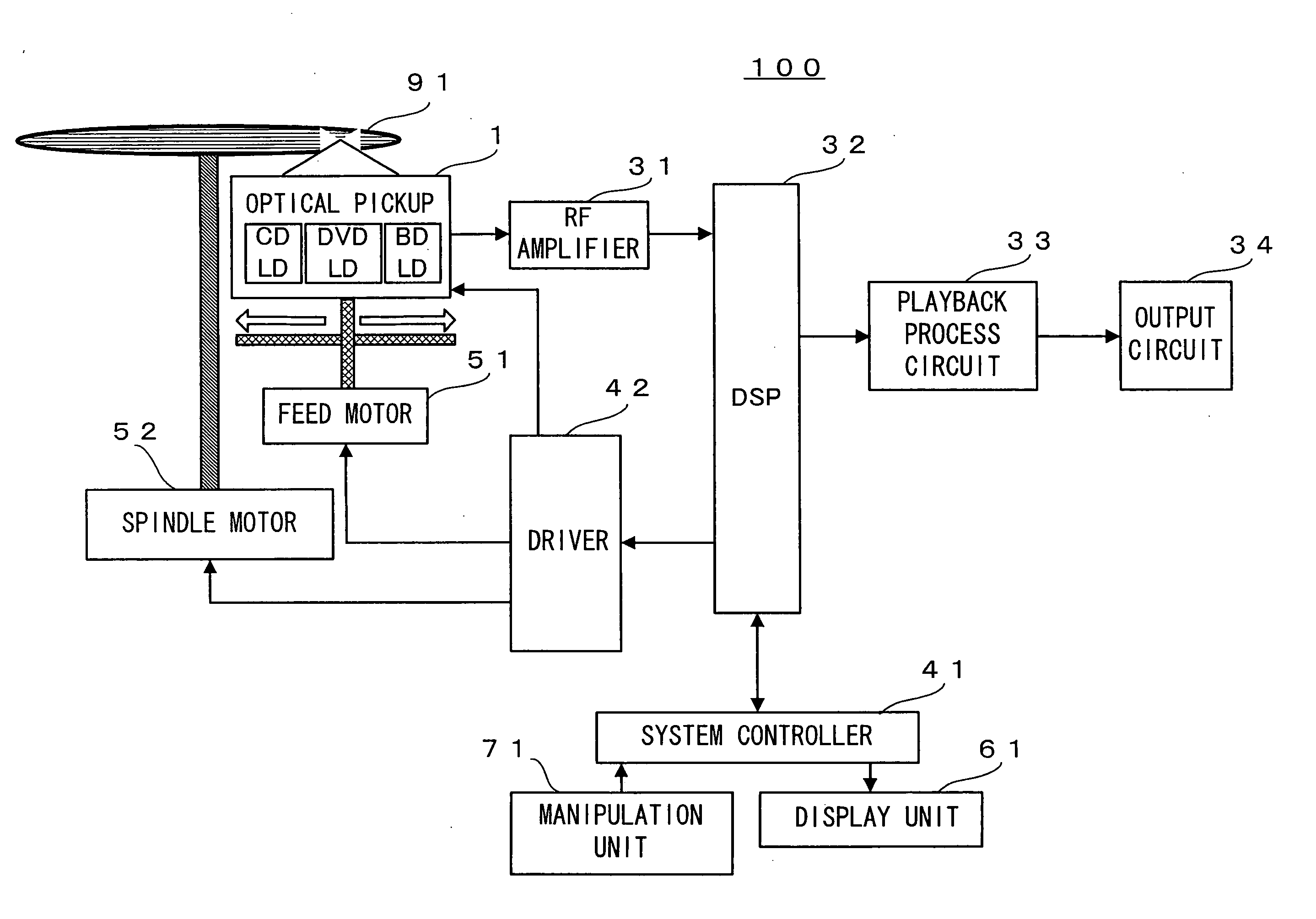
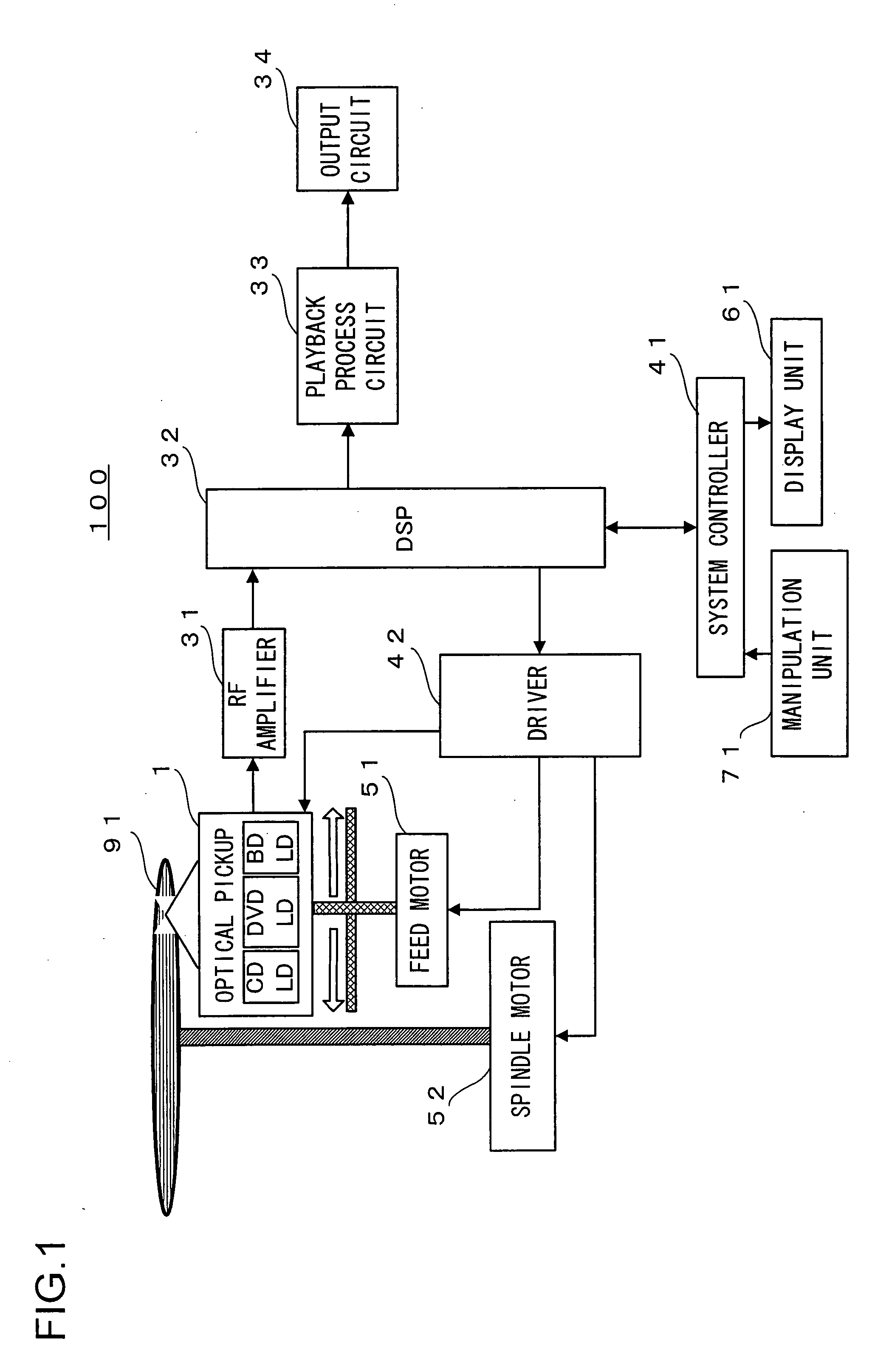
[0044]FIG. 1 is a block diagram of a disk player 100 (namely, optical disk apparatus) according to one embodiment of the invention. The disk player 100 includes an optical pickup 1, an RF amplifier 31, a DSP (Digital Signal Processor) 32, a playback process circuit 33, an output circuit 34, a system controller 41, a driver 42, a feed motor 51, a spindle motor 52, a display unit 61 and a manipulation unit 71.

[0045]The optical pickup 1 projects a light beam onto an optical disk 91, and it reads various information items, such as vocal information and video information, recorded on the optical disk 91 (CD, DVD or BD). This optical pickup 1 is provided with a laser diode for the CD, a laser diode for the DVD, and a laser diode for the BD.

[0046]The RF amplifier 31,...


PUM

PropertyMeasurementUnit
radial inclination angleaaaaaaaaaa
voltageaaaaaaaaaa
reflectionaaaaaaaaaa

Abstract

The whole reflection signal and a tracking error signal are detected while an objective lens is being moved in the radial direction of an optical disk, and the temporal difference between a time at which the value of the whole reflection signal becomes a maximum and a time at which the value of the tracking error signal becomes zero is detected in a predetermined time period. In addition, a value which is obtained by dividing the temporal difference by the time period of one cycle of the tracking error signal is acquired as a tilt appearance magnitude. Relational information in which a tilt appearance magnitude and a tilt correction magnitude corresponding to the tilt appearance magnitude are associated is read out, and the relational information read out and the current tilt appearance magnitude detected by a tilt-appearance-magnitude detection circuit are compared, thereby to determine the tilt correction magnitude necessary for a tilt correction. The tilt correction magnitude is notified to a tilt correction circuit, and is used in making the tilt correction.

Description

[0001]This application is based on Japanese Patent Application No. 2006-326897 filed on Dec. 4, 2007, the contents of which are hereby incorporated by reference.BACKGROUND OF THE INVENTION[0002]1. Field of the Invention[0003]The present invention relates to an optical disk apparatus for reading out information recorded on an optical disk, and more particularly to an optical disk apparatus which can correct a coma appearing due to the warp of an optical disk.[0004]2. Description of Related Art[0005]In recent years, optical disks such as a compact disk (hereinbelow, termed “CD”) and a digital versatile disk (hereinbelow, termed “DVD”) have spread and have come into general use. In addition, an optical disk apparatus exists as an apparatus for reading out and playing back information recorded on an optical disk, for example, vocal information or video information. By way of example, a CD player, a DVD player, or a CD-ROM drive connected to a personal computer is mentioned as an optical...

Claims


Application Information

Patent Timeline
Patent Type & Authority Applications(United States)
IPC IPC(8): G11B7/09
CPCG11B7/0945G11B7/0956G11B2007/0006G11B7/13927G11B7/1275
Inventor SHIMIZU, SHINYA
Owner FUNAI ELECTRIC CO LTD
Why Eureka
Try Eureka